GizMow
Robotic lawn mower

Disclaimer
Why?

Because mowing many acres is time consuming.
And kinda dull.
And because it's a good test-bed for other agricultural machines. The mowing deck could be replaced with other things - a bucket to carry tools / rocks / weeds / spray tool / weeding instrument, a camera .. etc.
The CAD concept
Videos
Non-autonomous (manually controlled) mowing robot ('GizMow-1') initial test
medium
small
Non-autonomous (manually controlled) mowing robot ('GizMow-1') mowing grass (turn down your volume!)
medium
small
Non-autonomous first test around the house paddock ('GizMow-2') [and yes, the control box is only attached by a loose strap].
medium
small
Autonomous simple grid test in house paddock ('GizMow-2') 8x speedup.
link
Reel Mower Experiment
Well .. it seemed like a really good idea at the time, but a manual reel mower this is actually a very inefficient solution. Particularly as it would put considerable strain on the gearboxes of the motors.
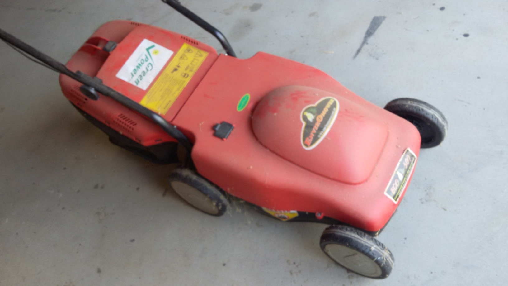
A rotary mower is a better solution- it won't put as much stress and strain on the gearbox. This one is a battery operated electric rotary mower. These are easier to use with a robot than a petrol-powered mower.
They run on batteries already, and could even share the batteries with the drive mechanism.
They are generally lighter, and hence easier to work with.
They can be turned on and off with a relay, and are therefore easier to fully automate.
The controller can monitor the motor current to detect stalling, near-stalling, or thermal cut-out.
But there are also disadvantages of a battery mower.
They are not good at getting through thick grass.A decision was made to make a frame large enough to mount either a battery or petrol powered mower to allow experimentation with both.
Considerations with a petrol-powered mower
One of the issues with a standard push mower is stalling. If you hit a thick clump of vegetation, the mower is prone to stall. A human operator will intuitively either lift (tilt) the mower or reverse it to prevent the stall. Further, a human operator tends to adapt the speed of pushing the mower according to the toughness of the vegetation - the mower gets pushed more slowly through the thicker grass.

Bar blades
Rotating machetes - long heavy blades

Swing blades
Small blades, which can bend back if they hit something
Many modern mowers reduce the need for this process in several ways. Firstly they have a governor, which effectively tries to keep the motor at constant speed. It's like an auto-throttle which revs the engine when it starts to slow down. Secondly, they use swing blades mounted on a disk, instead of the 'rotating machetes' model.
With swing blades, only a small amount of grass is actually being cut at a time. Too much grass, and the blades get pushed back (though the are unlikely to in the photographed example because they are so badly rusted). This might reduce the quality of the cut, but it means the motor is less prone to stalling.
This is both good and bad news for a robot mower - it may not stall, but the robot won't get good feedback to enable it to slow down on thick grass to get a good cut. A servo-controlled throttle could be installed, but it would have to interact with the governor in subtle ways (or the governor would have to be removed).
This would be a good reason to monitor the RPM of the engine.
Components
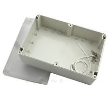 |
Box | EBay | A box. A big box. Always use a bigger box. Jaycar don't stock good boxes this size, and ordering them online is almost as much as buying locally because of the size. |
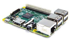 |
Raspberry Pi-3 | Core Electronics | The brain of the rover. |
 |
Voltmeter | EBay | Monitor battery charge and generally check that the voltages are okay. |
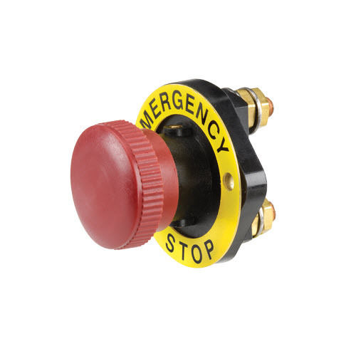 |
Latching Panic Button | EBay | This is essential. Rovers are temperamental, and large rovers are dangerous. |
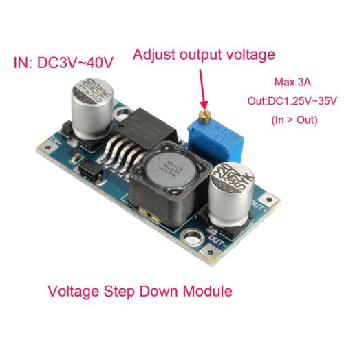 |
Step-down Power Supply | EBay | To (back-)power the Raspberry Pi. Don't use one of these, they are not reliable. Use a proper automotive one. |
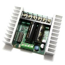 |
Sabertooth 2x25 | Dimension Engineering | Main drive motor controller. These are great. |
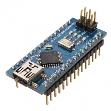 |
Arduino Nano | EBay | Arduinos are better than Raspberry Pis at talking to 5V peripherals (like the EasyDriver), and doing repetitive grunt work to take the load of the Pi. |
 |
WiFi Dongle | EBay | For communicating with WiFi network (including the RTKLIB base station). |
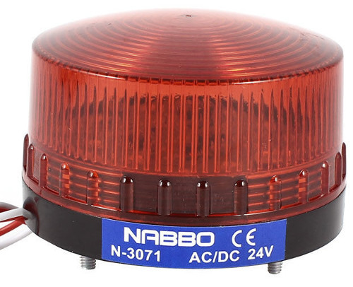 |
Warning Strobe | EBay | Robots are dangerous. Warn people about this. |
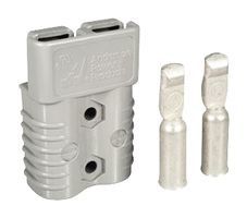 |
50A Anderson Plugs | EBay | May be required to connect battery or drive motors. Cheap when bought in bulk. |
 |
Pneumatic Wheels | Bunnings | Far better than the ones which came with the wheelchair. I had to take out the centres of these with an angle grinder and a vice. In the end they fit pretty well. Some people complain that these cheap tubes don't hold pressure, but I haven't had any problem. |
Process - GizMow-1

Most of the paraphernalia which comes with an electric wheelchair is useless unfortunately. The only parts of the chair that were re-used for this project were the motors (including the gearboxes and axles), and the batteries.
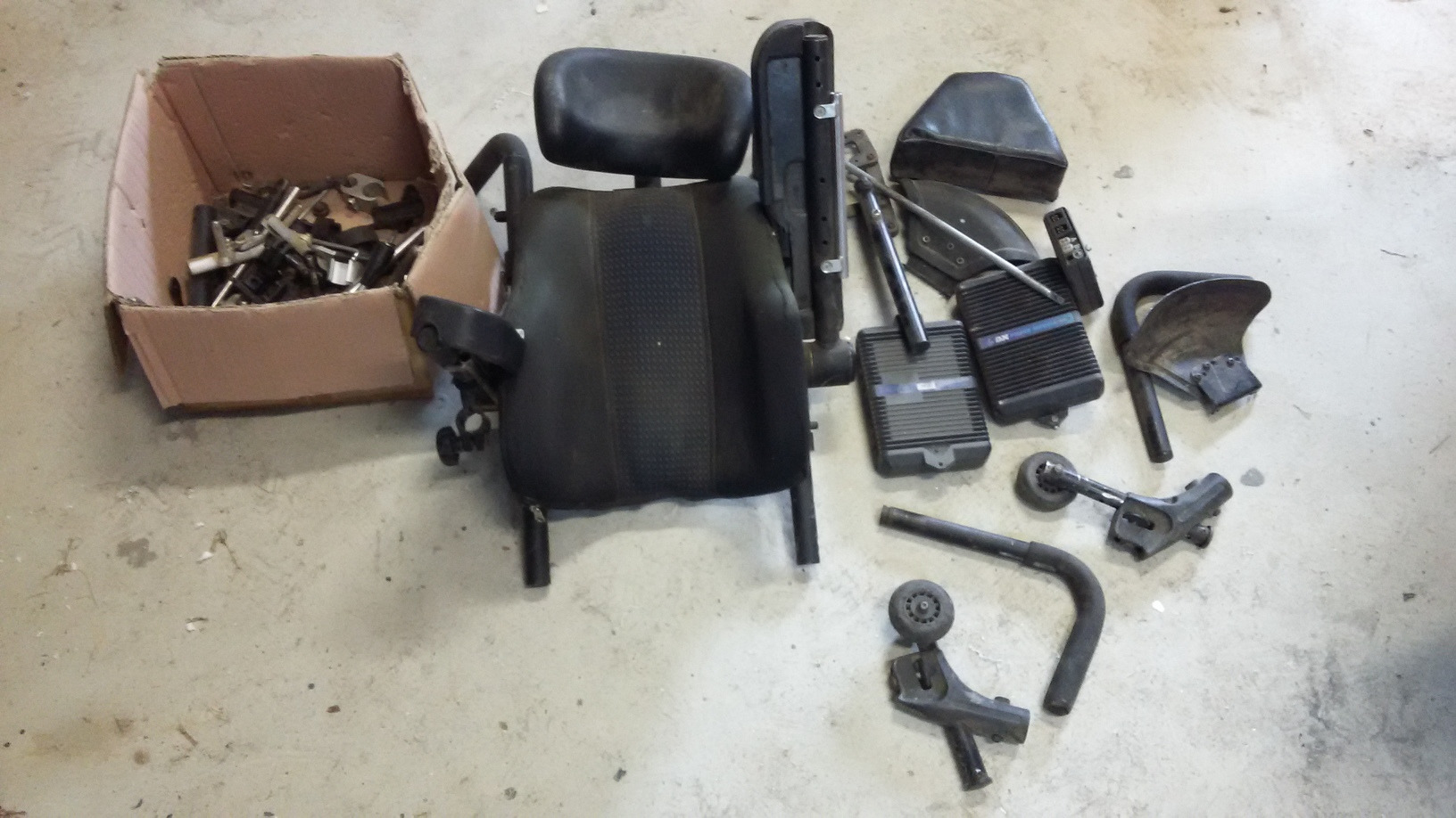 Disassemble any human-interface components on the chair.
Photograph the model numbers on the motors and batteries in case the labels are damaged or made illegible in the clean-up, or any subsequent trauma.
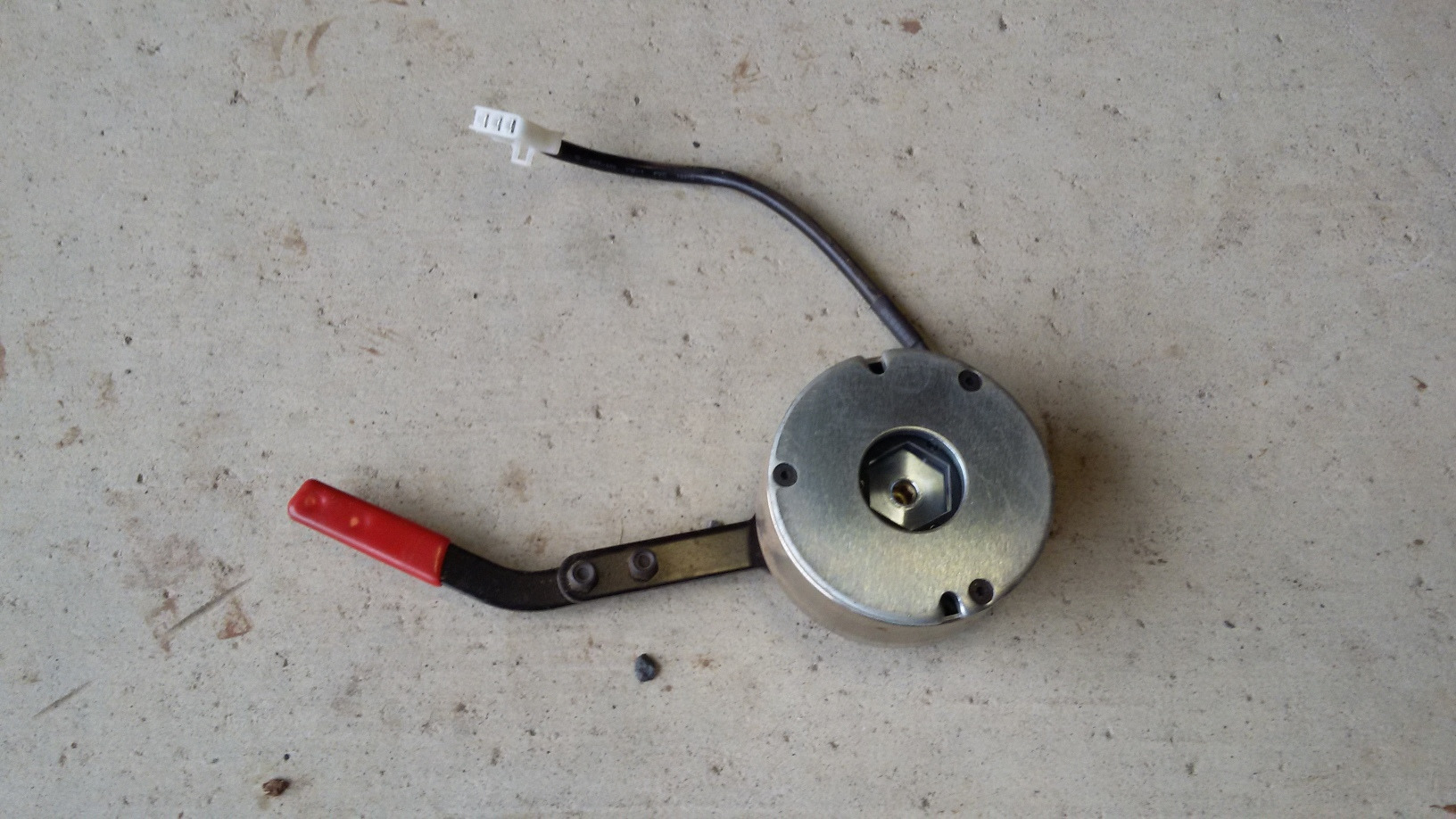 Take out the brakes from the motors. Usually this involves unscrewing the plastic cover from the ends of the motors, unscrewing the brakes and cutting a few wires.
Remove the existing motor controller(s). They are probably of little use - in particular they have safety features built-in like turning off if the brakes are not detected. They can be reprogrammed, and modified, but that is a lot of reverse engineering. Fitting a Sabertooth 2x25 is an easier option.
Work out how to get power to the Sabertooth 2x25 from the batteries, and to the motors. Anderson plugs are good, but there are many others too. This may mean cutting the existing wires (from the battery and to the motors) and soldering the plugs.
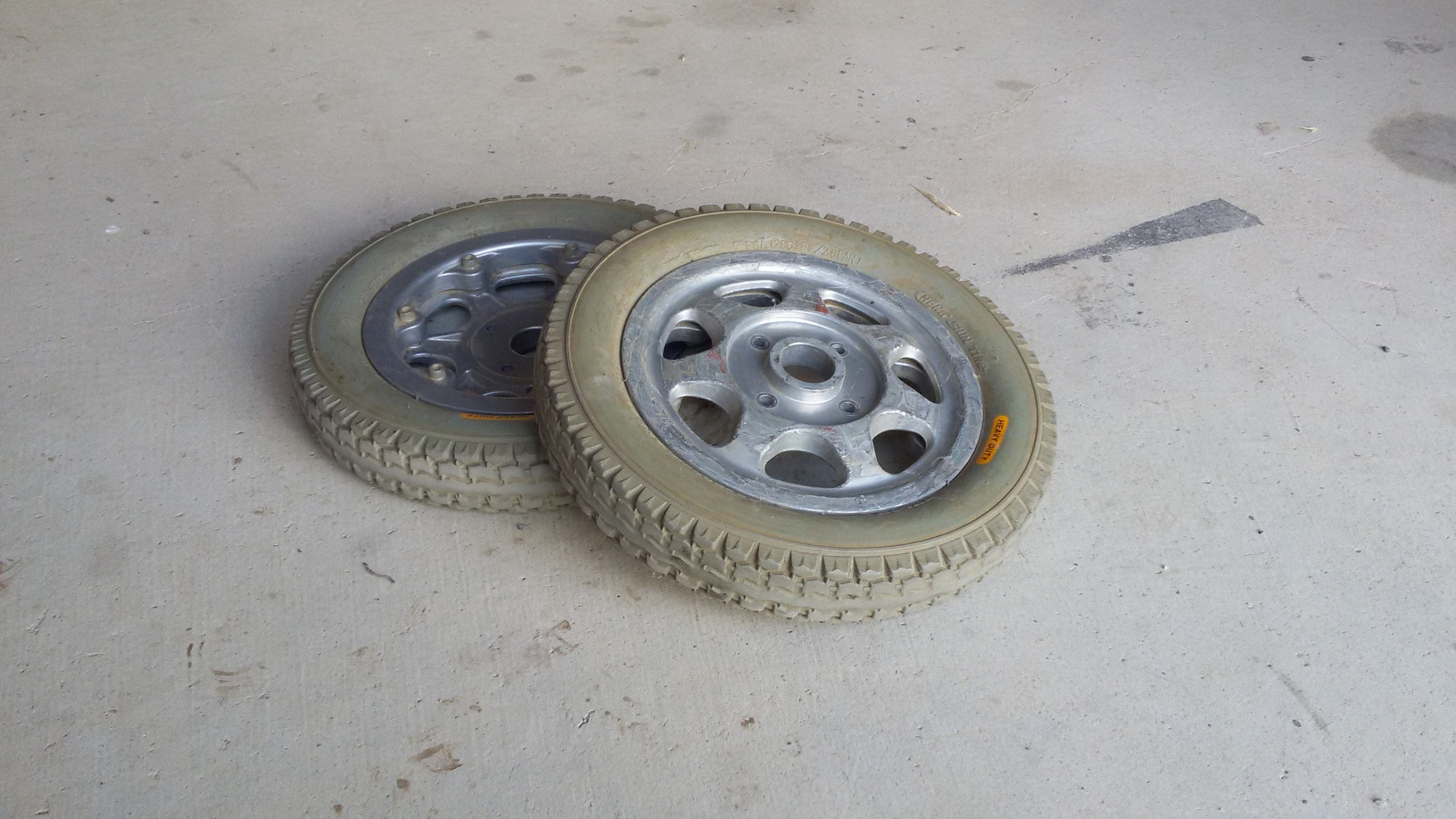
The standard wheels were too big and too narrow, and not pneumatic. Replaced with small pneumatic wheels.
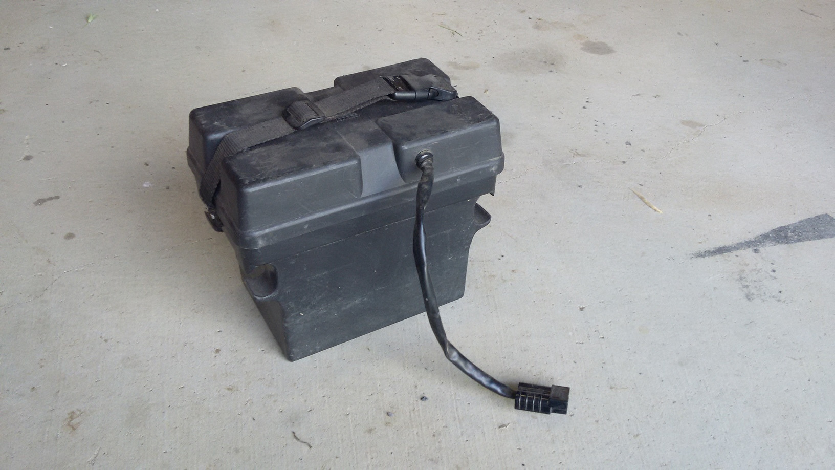
Some wheelchairs actually have water-resistant battery cases for the batteries. These are great for rough or wet terrain. Unfortunately They are also sometimes hard to fit into the available space. This one mounts well on two elongated tubes, but the tubes have an unusual cross-section, which is hard to come by.
You will need some box metal and a welder. 40mm box is pretty good for the frame of a mower.
.. welded and the mower seems to fit.
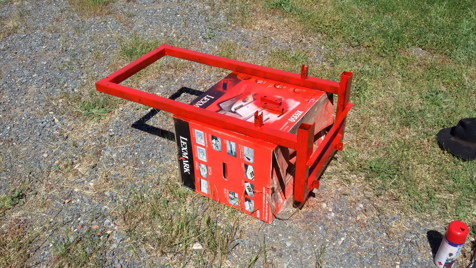
Painted red. Robots are dangerous. They should be red. A red strobe light is a good idea too.
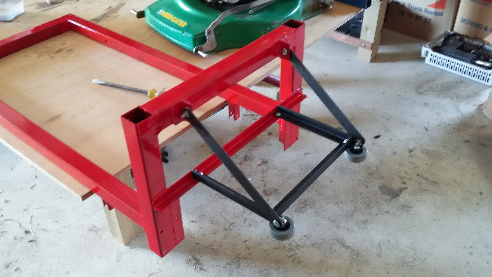
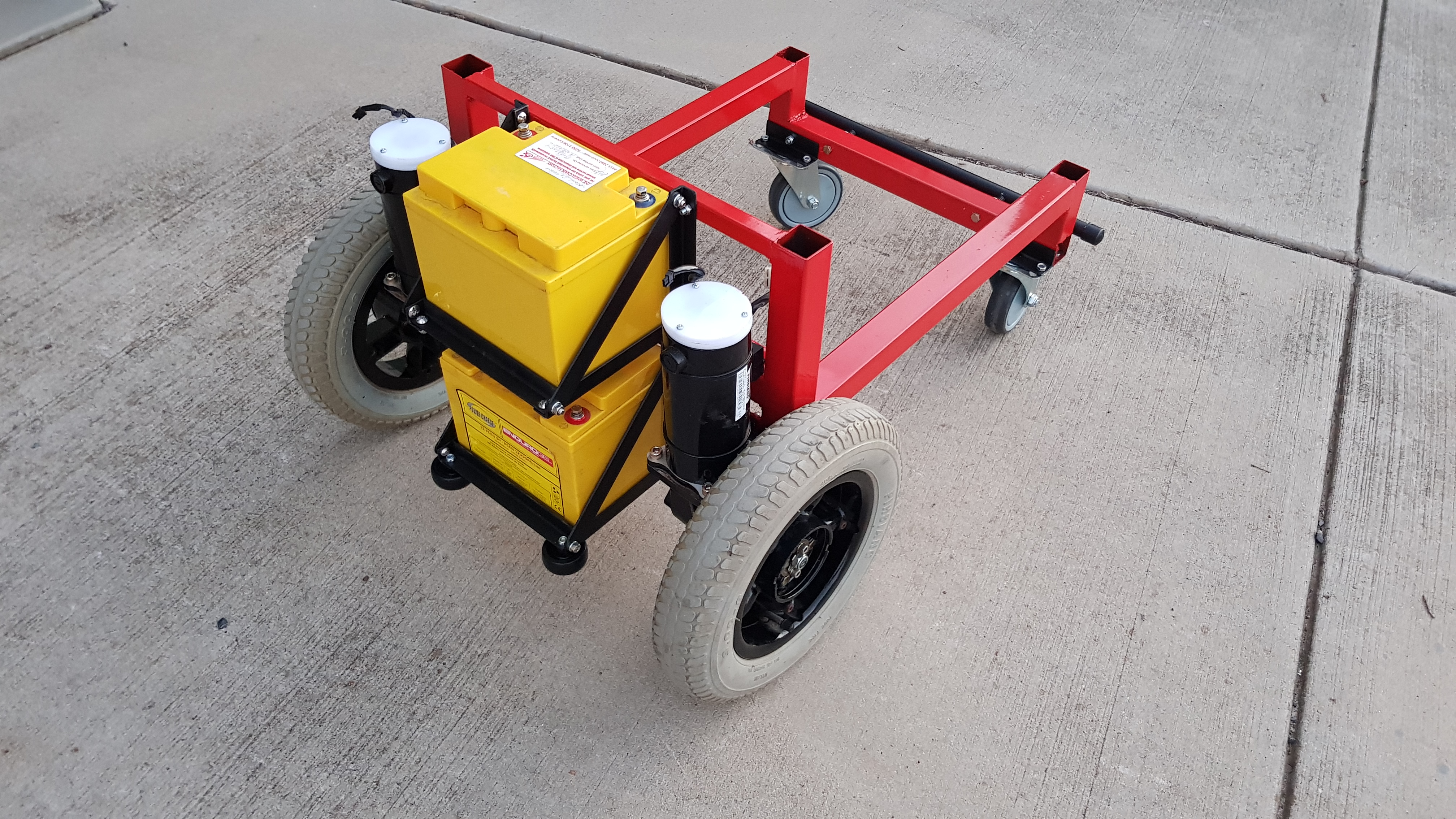
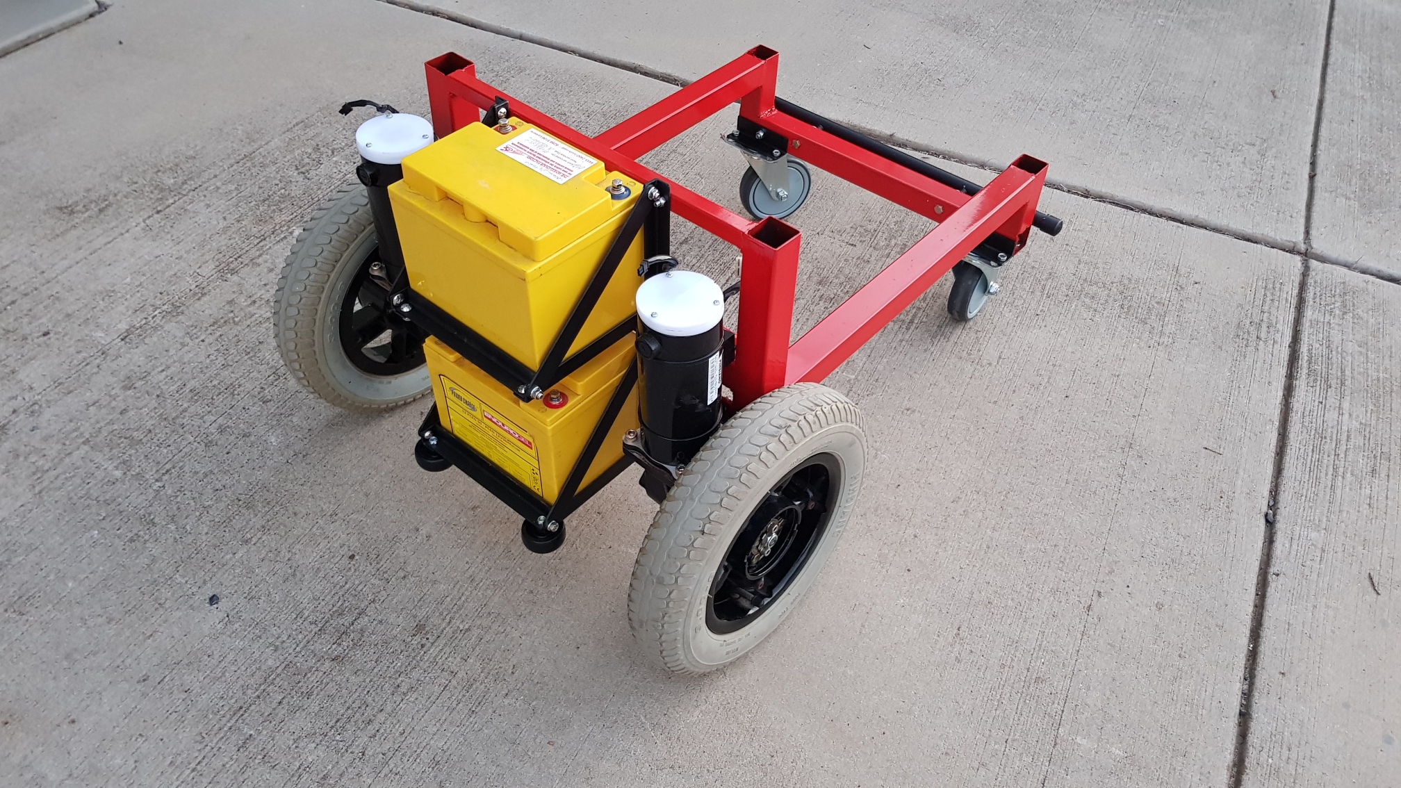
Backpack for the battery. The batteries are the heaviest part of the rover, and putting them in a back-pack will partially counter-balance the weight of the mower.
The horizontal wheels are for collision mitigation.
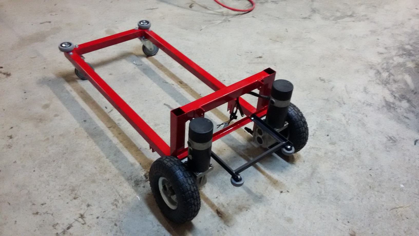
Motors attached. Note the $11 pneumatic wheels from Bunnings - better in so many ways. These will increase traction and leverage and decrease vibration.

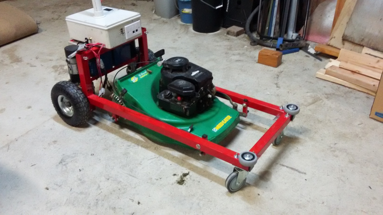
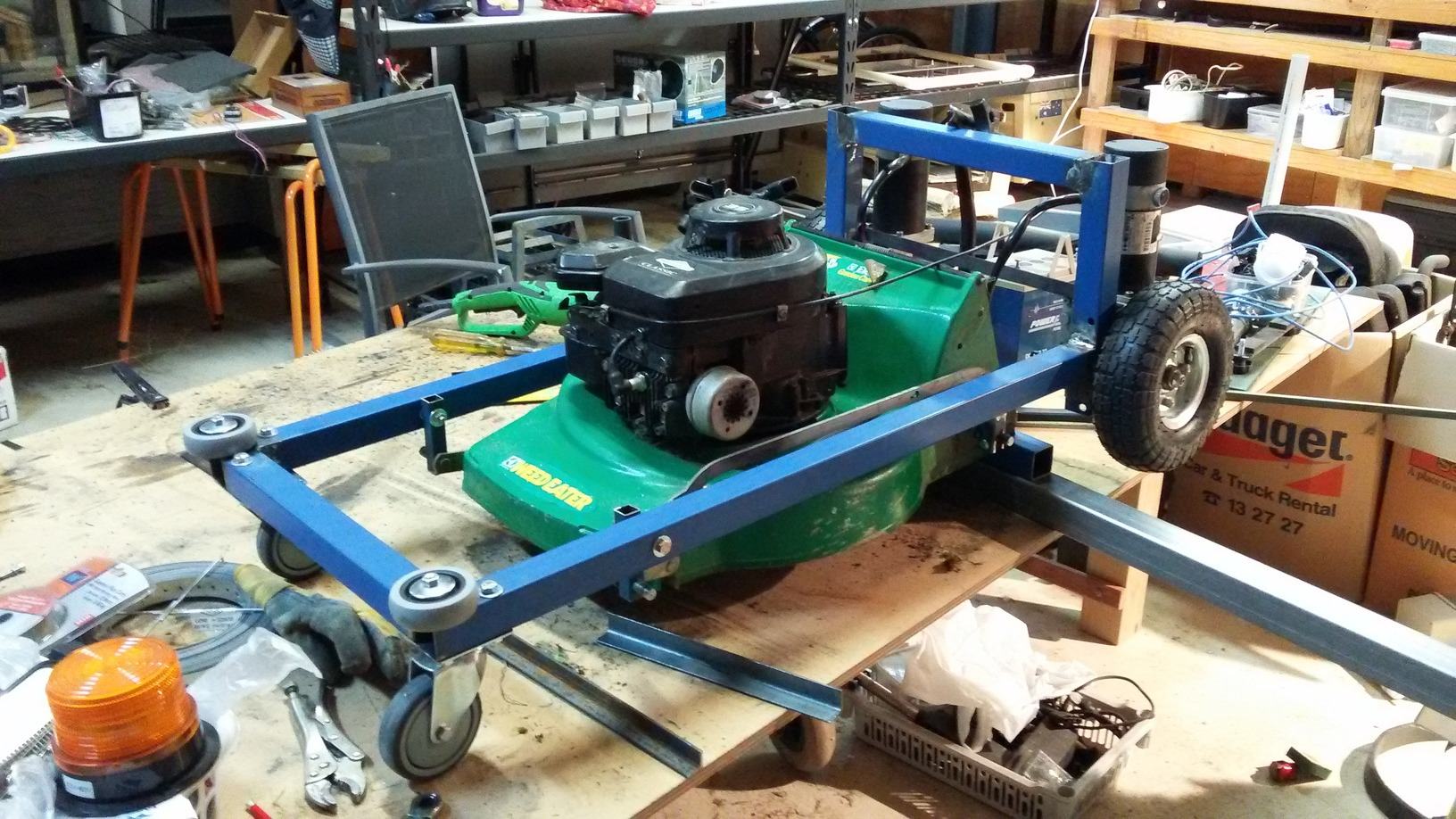
Mower remounted and batteries in the backpack. Not sure where to run the throttle cable.
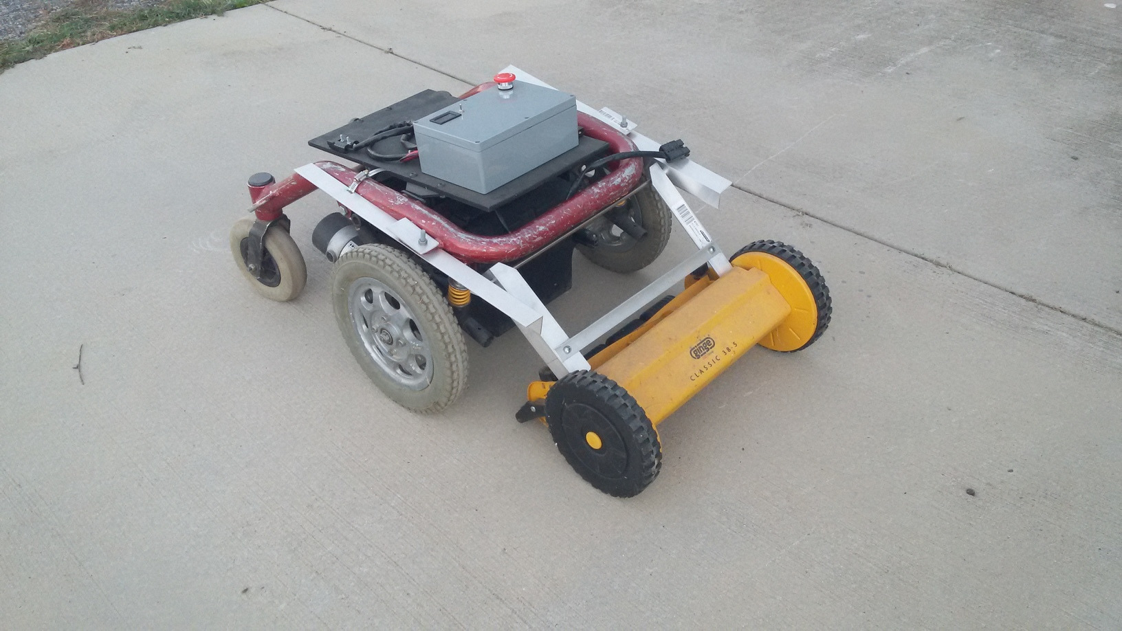
Process - GizMow-2
A custom mowing deck, which allows the rover to be shorter and more manoeuvrable.
 Pulling apart the chair.
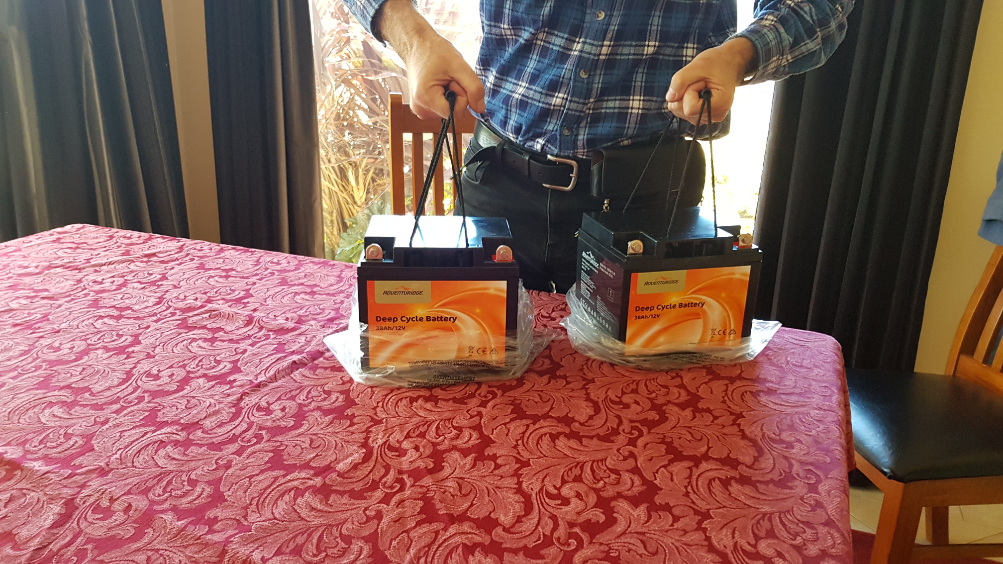 Aldi had a special on deep-cycle batteries.
Got up early and fought my way through the blue-rinse bargain hunters to pick up a pair of these.
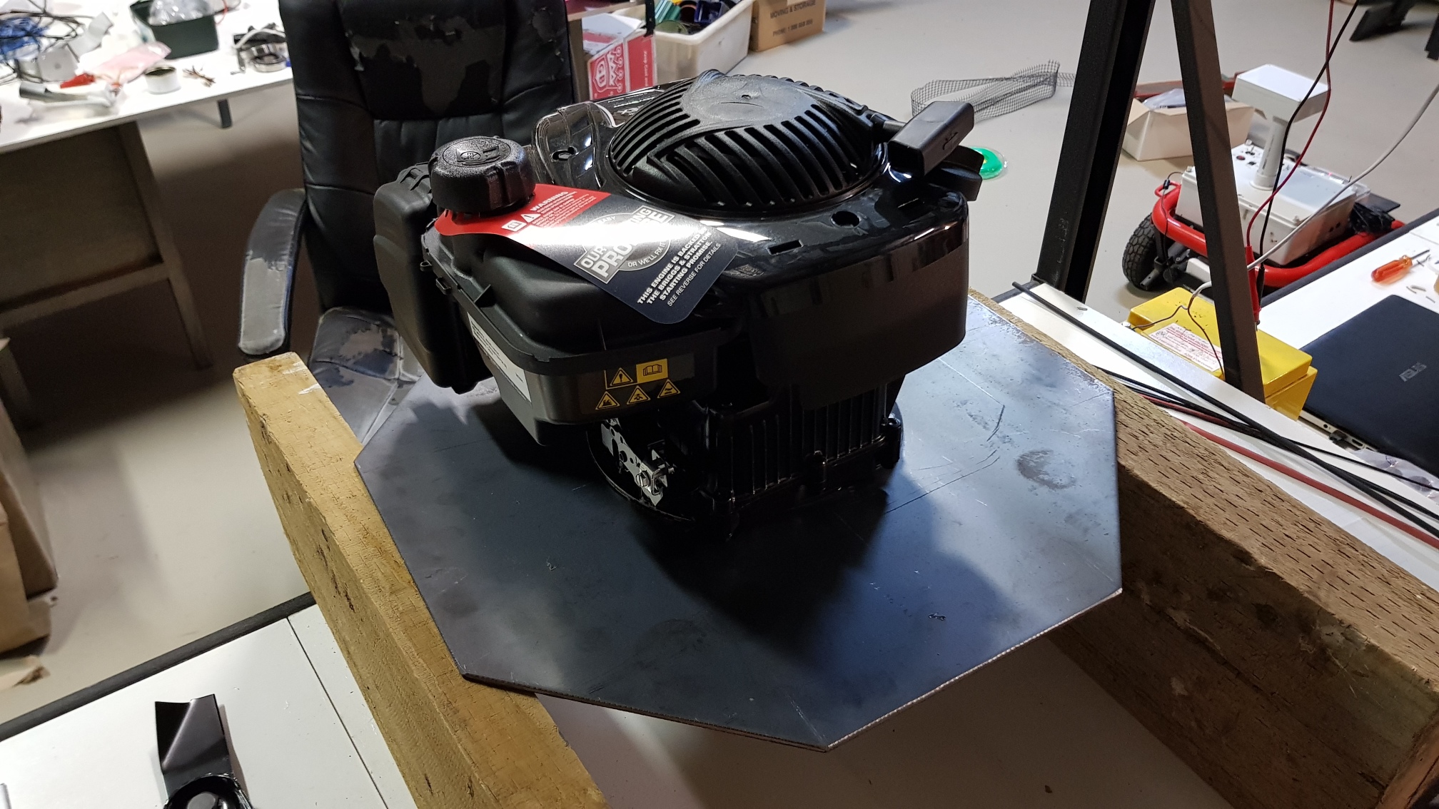 The engine on the octagonal plate.
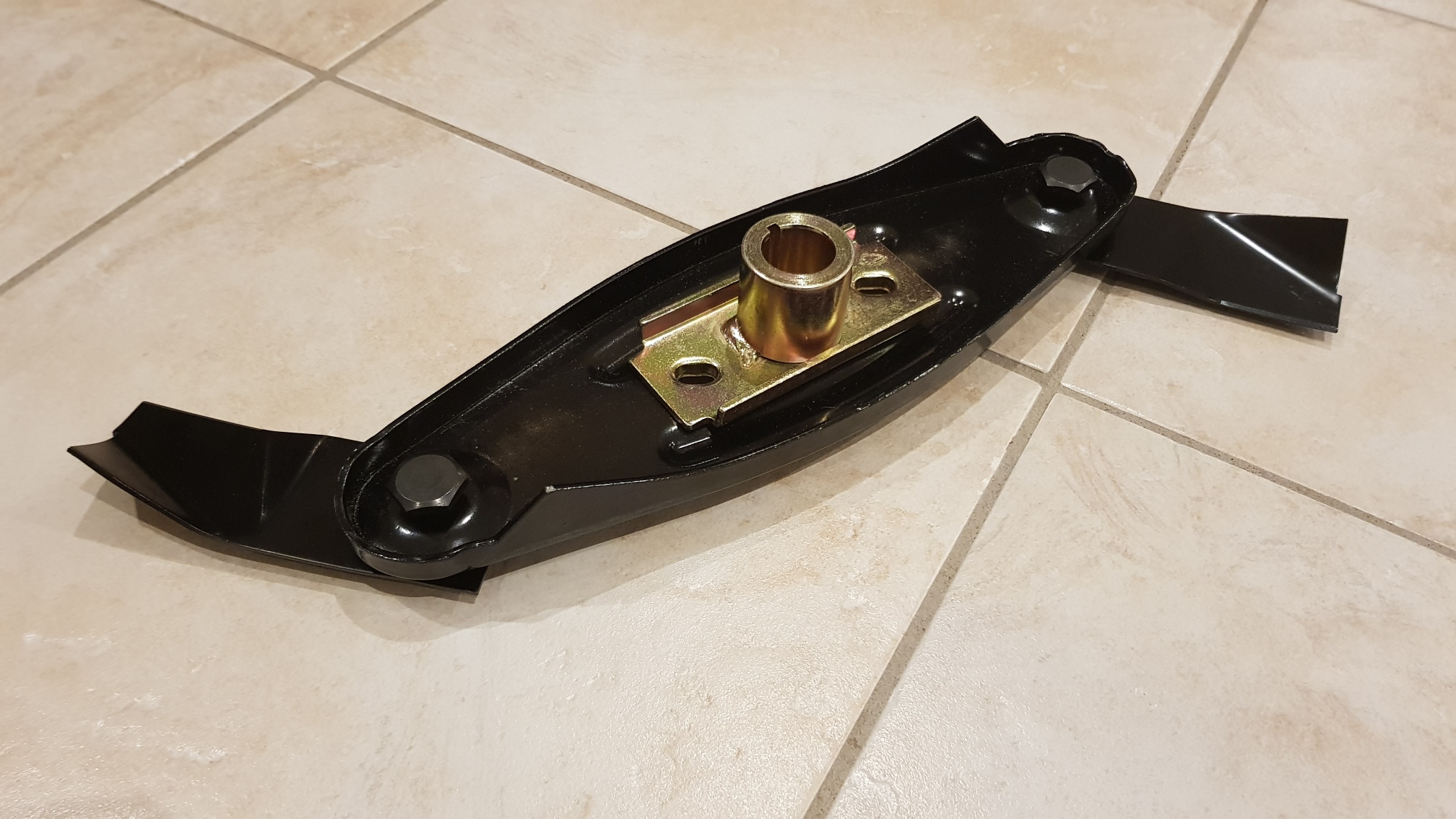 The blades - swing blades for a better cut and robust blade behaviour.
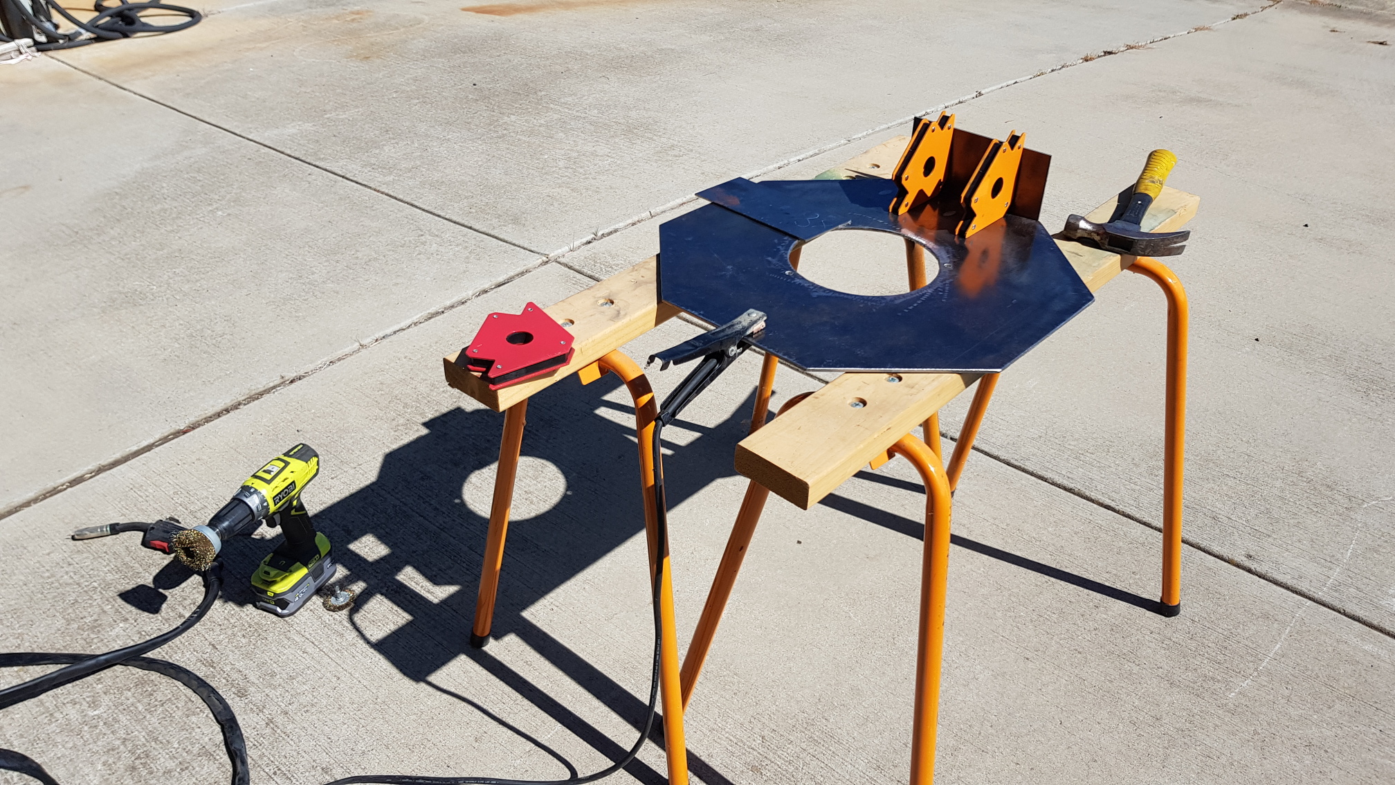 Welding the skirt onto the plate.
 Bunnings' cheapest dodgiest welder, and the welding skills to match.
Welding doesn't have to be good, just done with lots of redundancy.
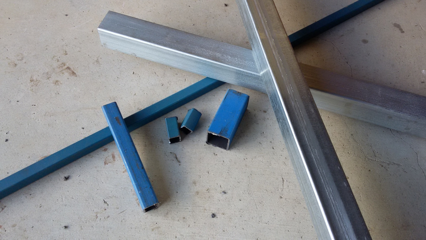
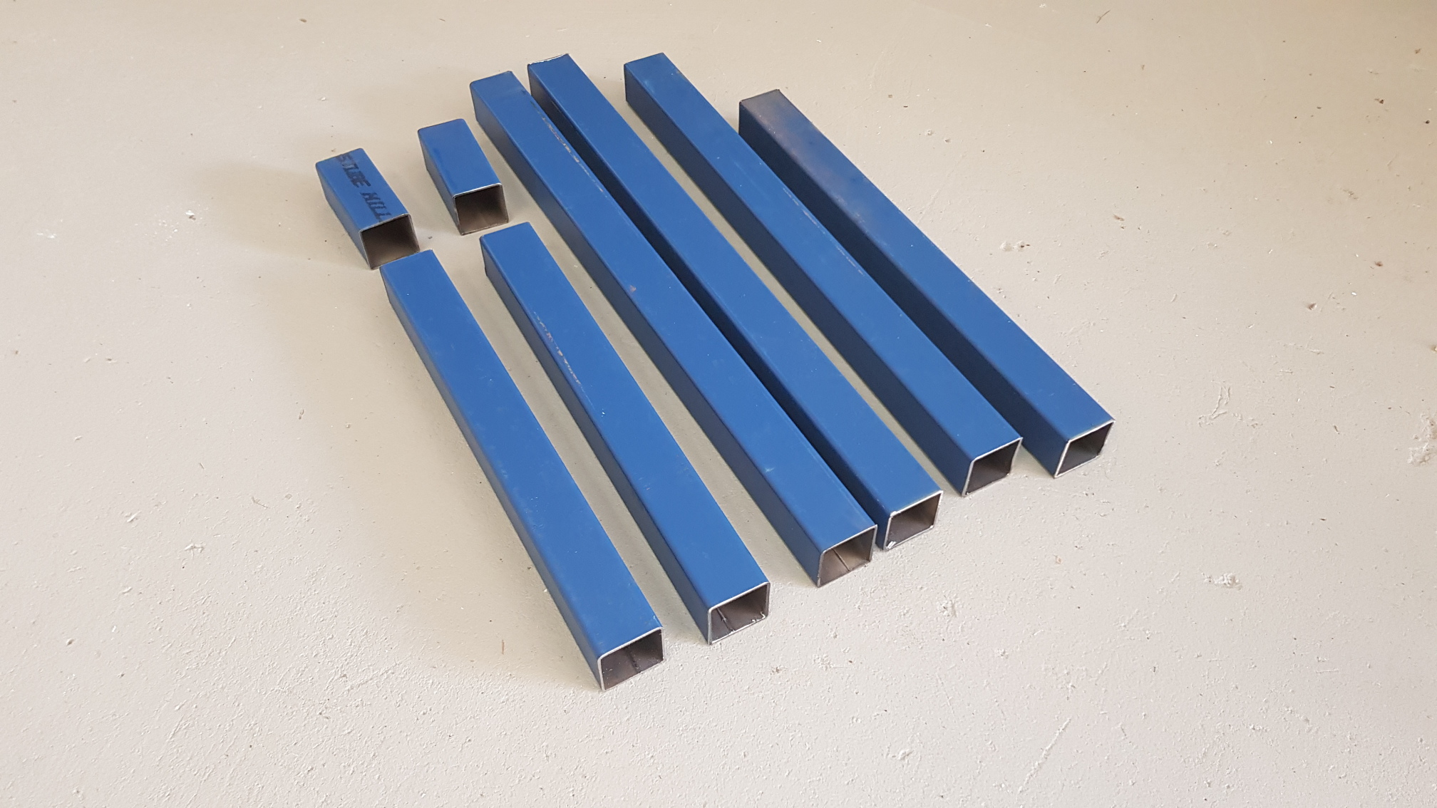 40mm square steel tube for the rover frame.
This seems like overkill, but (with 'challenged' welding ability) provides redundancy.
Also, it's much easier to drill into later for mounting things on. You can drill a lot of holes in 40mm box without compromising integrity.
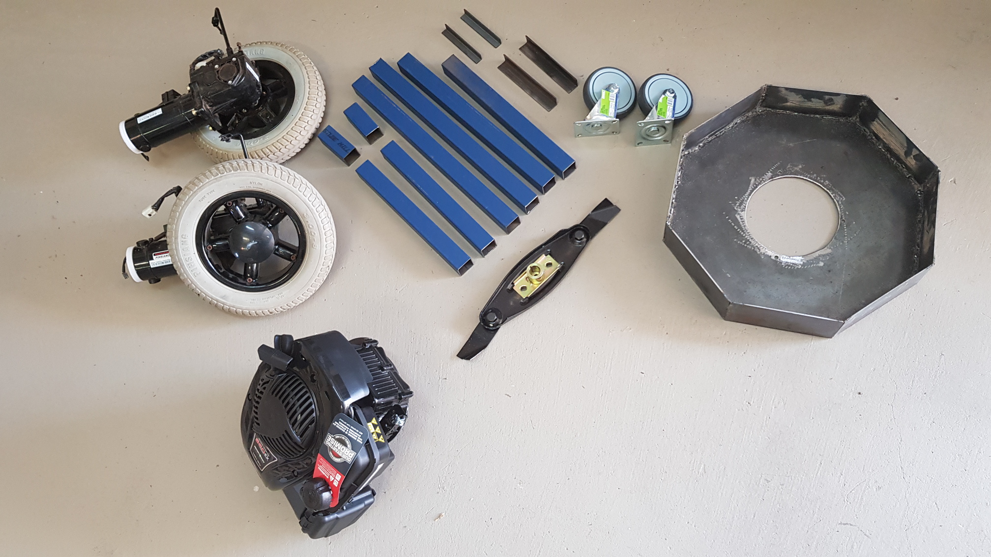 More parts.
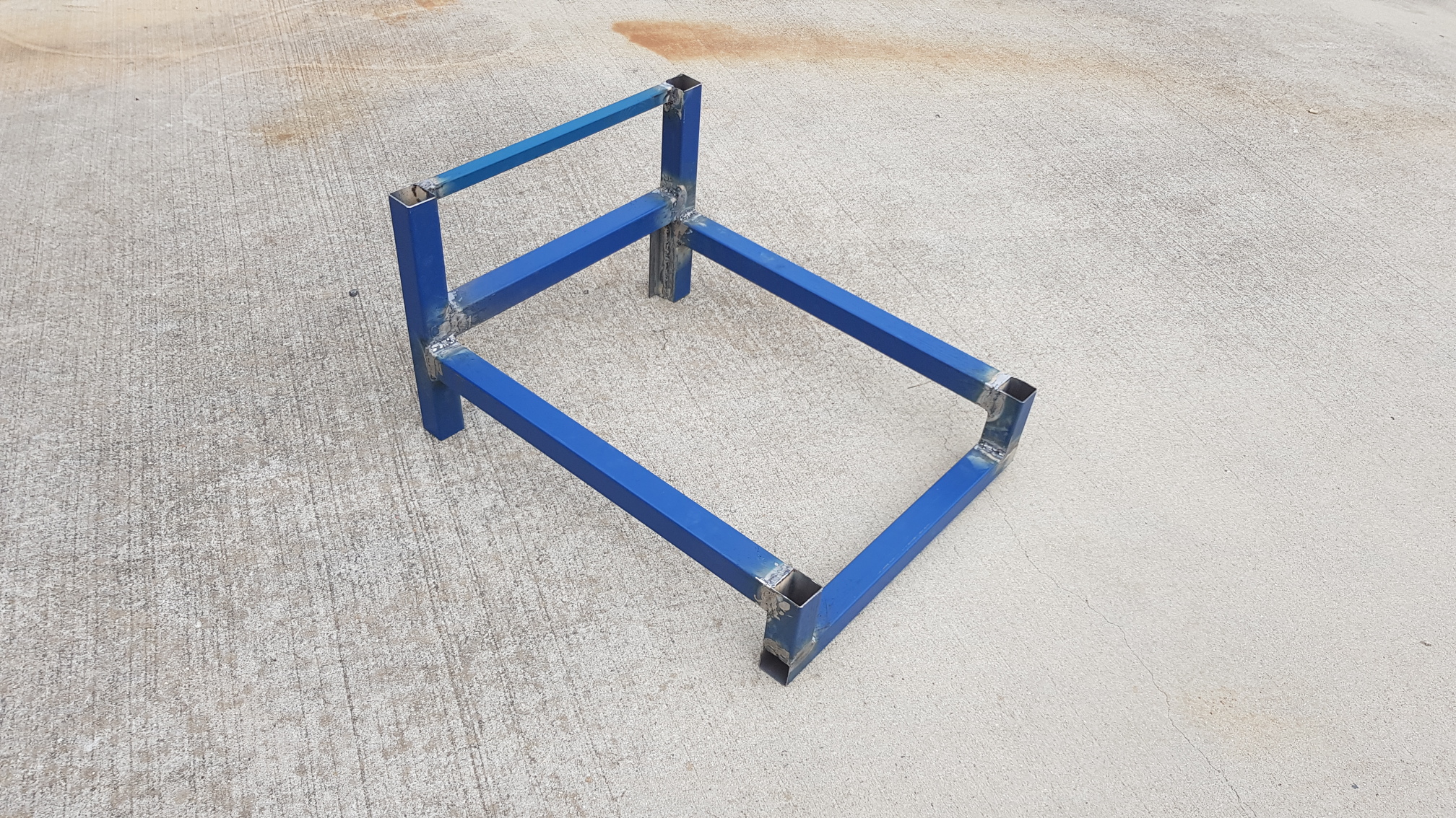 The welded frame.
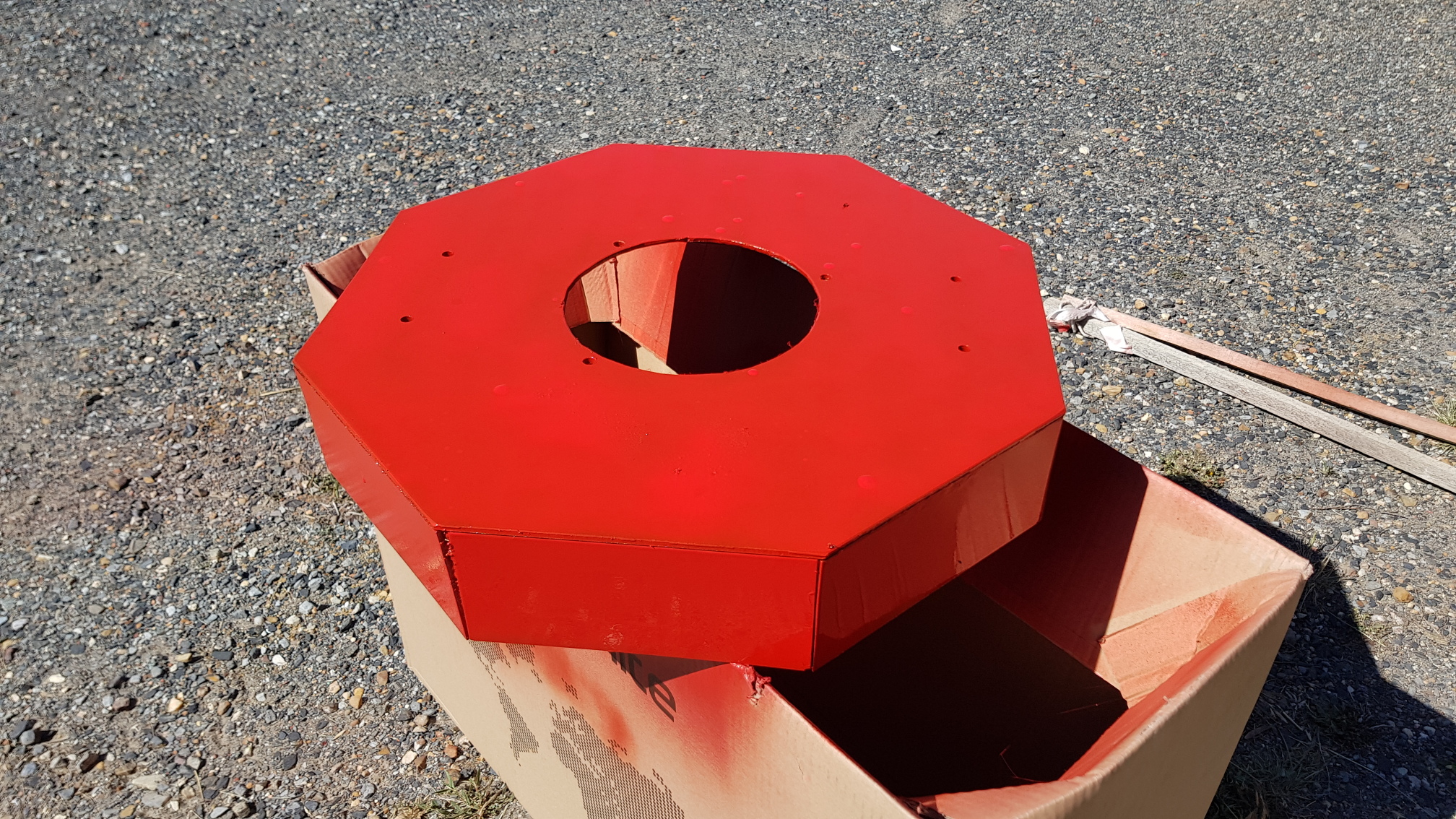 The mow deck.
Engine on the deck.
The mow deck.
Engine on the deck.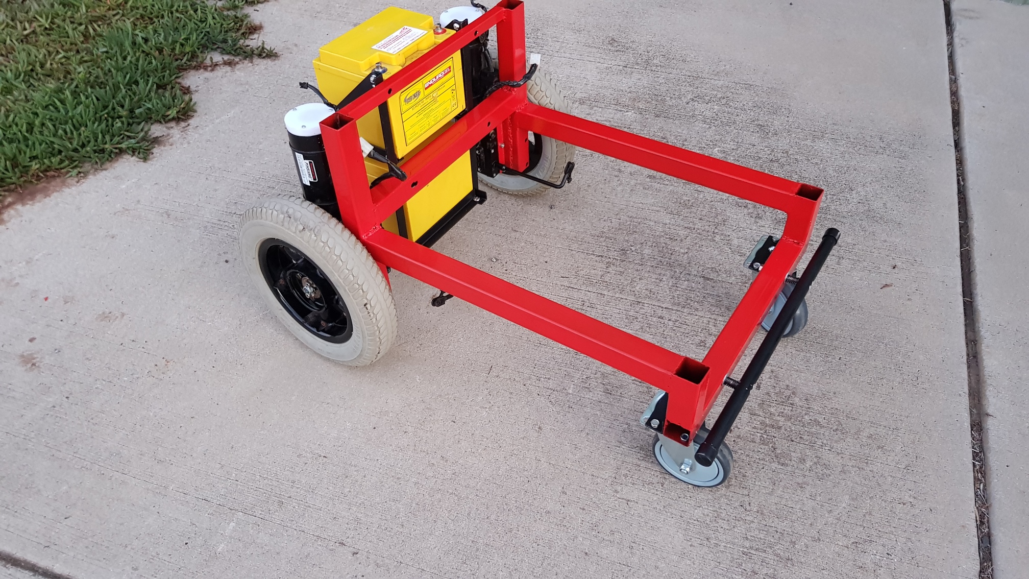 Welded and painted.
The collision detection bar is mounted no the front of the rover - no switches yet.
 Batteries on the back-pack.
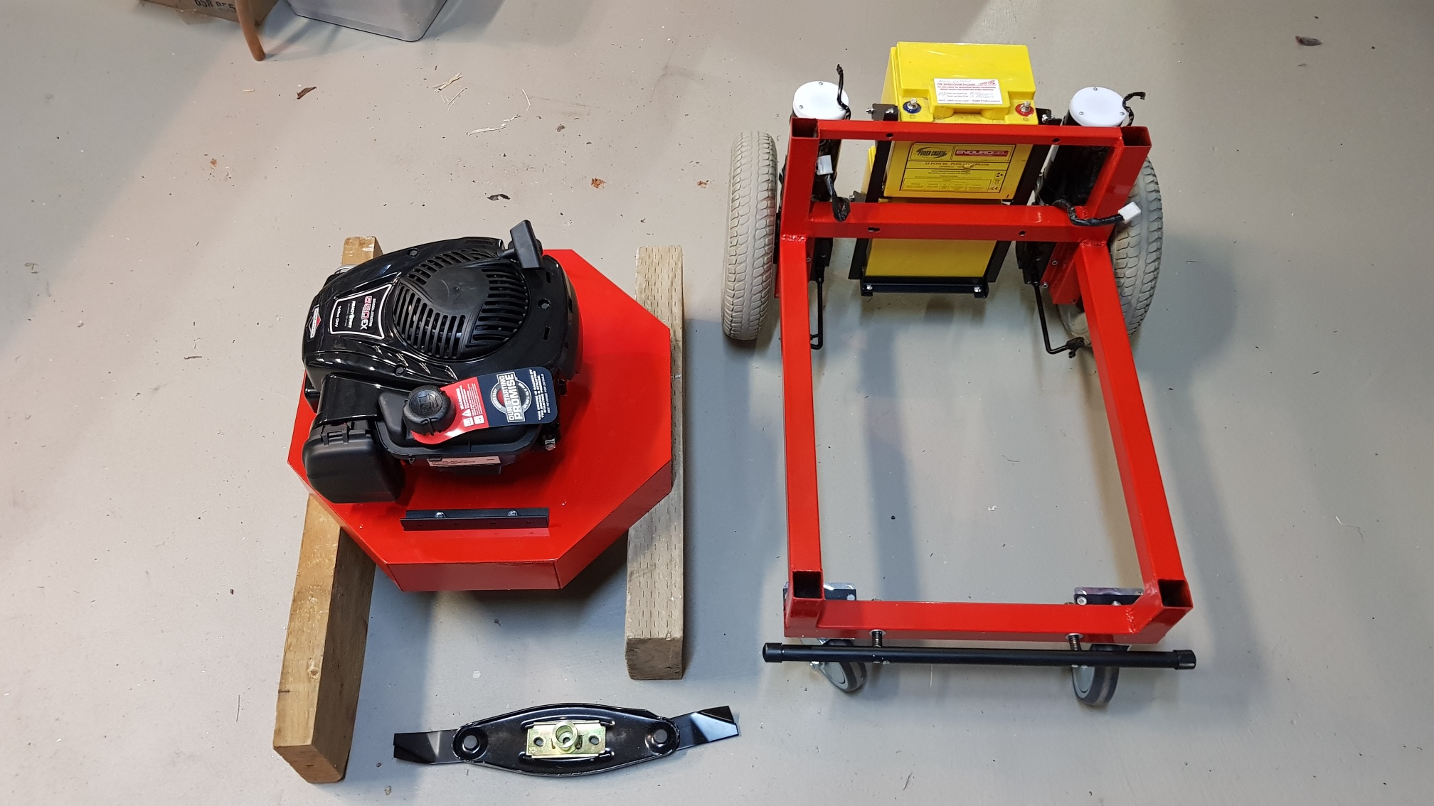 Some assembly still required
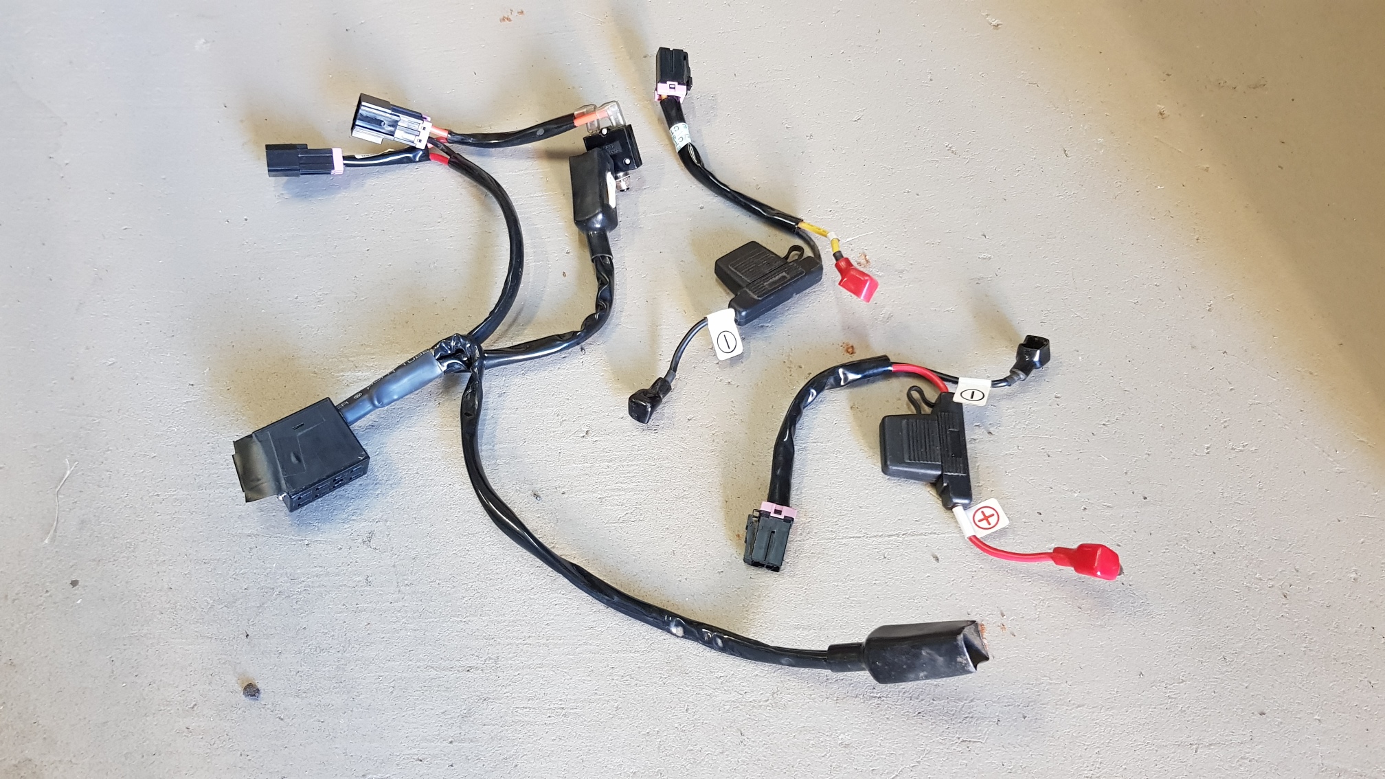 The original wiring loom from the wheelchair can be re-used.
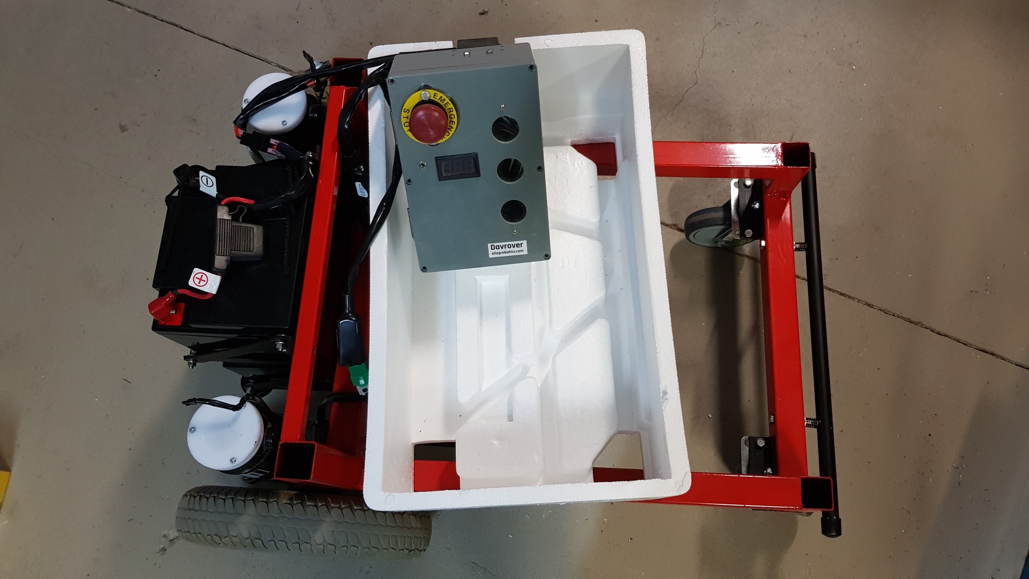 The Davrover control box can be reused as the test-control box.
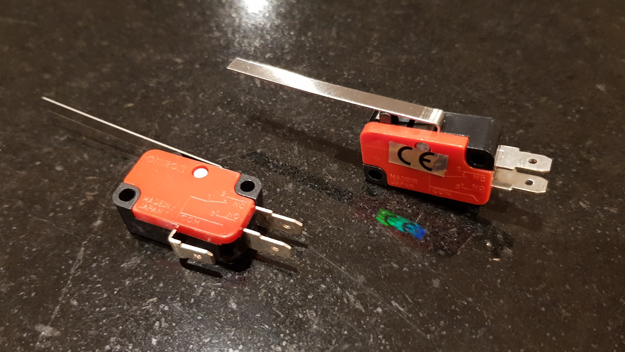 These micro-switches are good for collision detection.
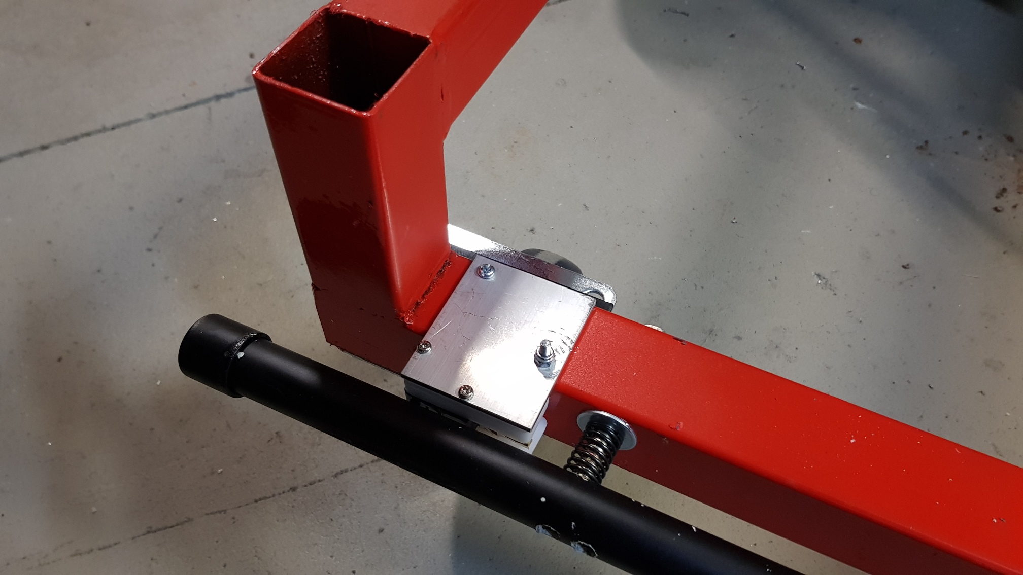
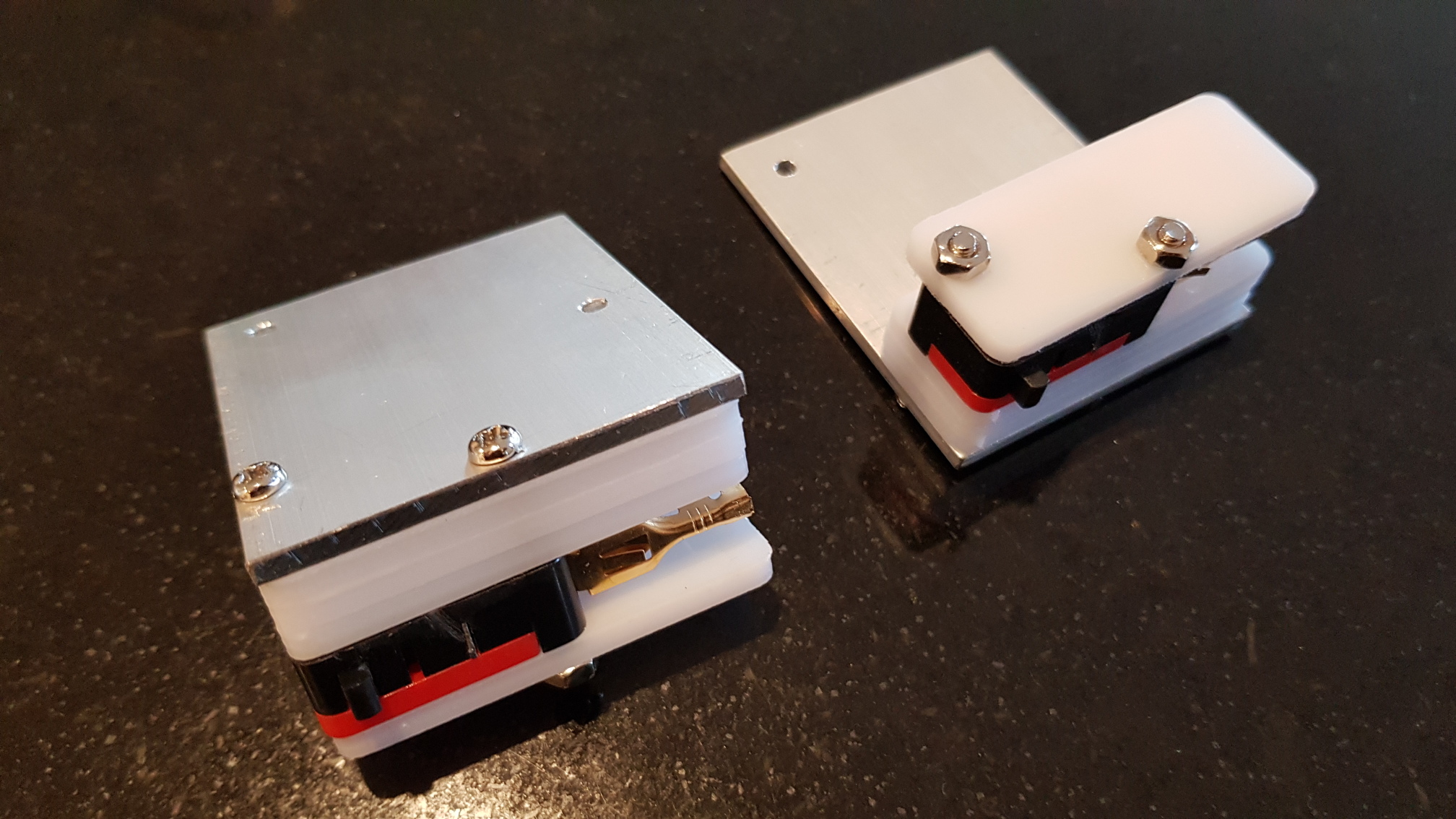 The lever and the 'normally off' terminal can be removed, and mounted between layers of CNCed acrylic.
The 'nib' (ie the actual press part of the switch) is just sticking out the front of these assemblies.
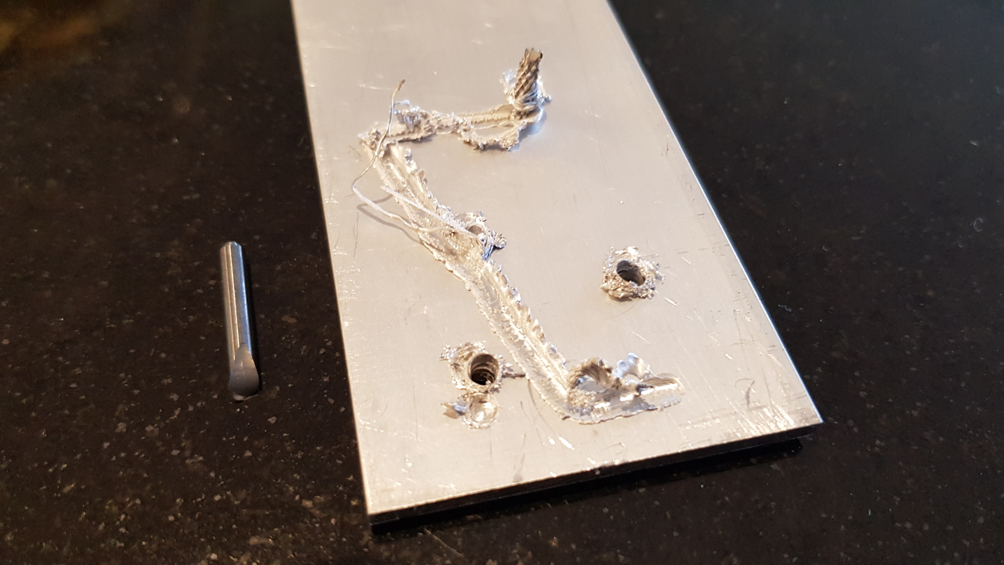 The top plate should have been CNCed too, but CNCing aluminium is harder than acrylic.
Yes, that is a broken milling bit stuck in melted aluminium. It was kind of spectacular.
I might leave Aluminium CNCing to the real professionals.
 The bumper switch mechanism mounted to the front of the robot.
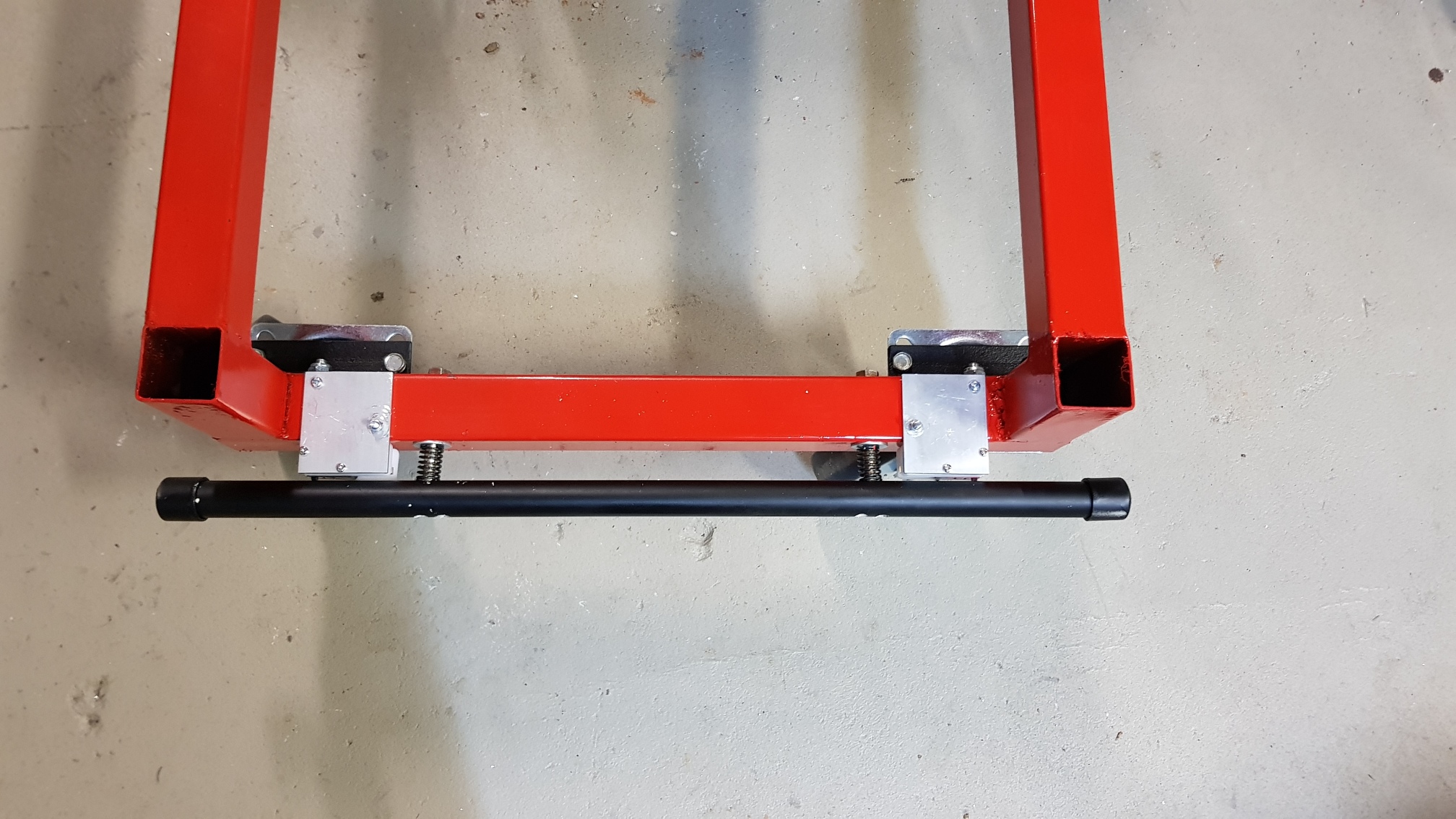 If the rover hits anything, the black bumpers will spring back and press the (normally ON) switches.
Hopefully the black plastic pipe is soft enough to bend or break before anything else, so the collision will be mitigated as well as detected.
The switches have also been placed so that even if one side of the bumper is caught and pulled, the opposite switch will still activate, and a collision will still be detected.
 Walking past a lawn mower shop and this little gem greets me.
I could have just purchased this lawn mower and reused the engine, blade assembly and deck, and thrown away wheels, handle and wheel mount brackets.
And the cost would have come out about the same. Hmm. Next time
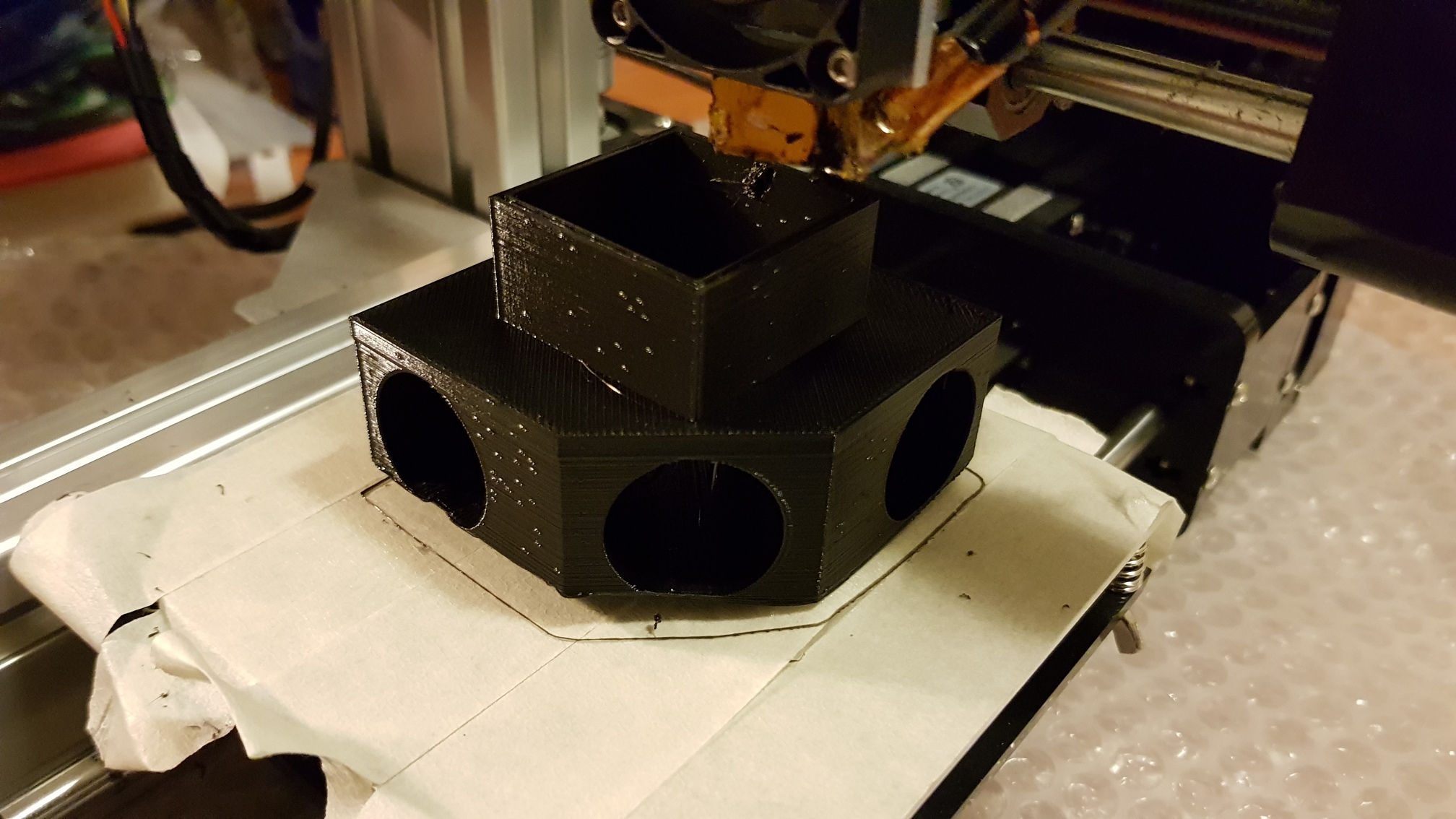 Printing a variation of the parking sensor mount which fits into 40x40x1.6mm steel square tube.
Yes, the bottom (well, top) of the sensor is peeling off the bed.
 Mounted on the rover with the looming done.
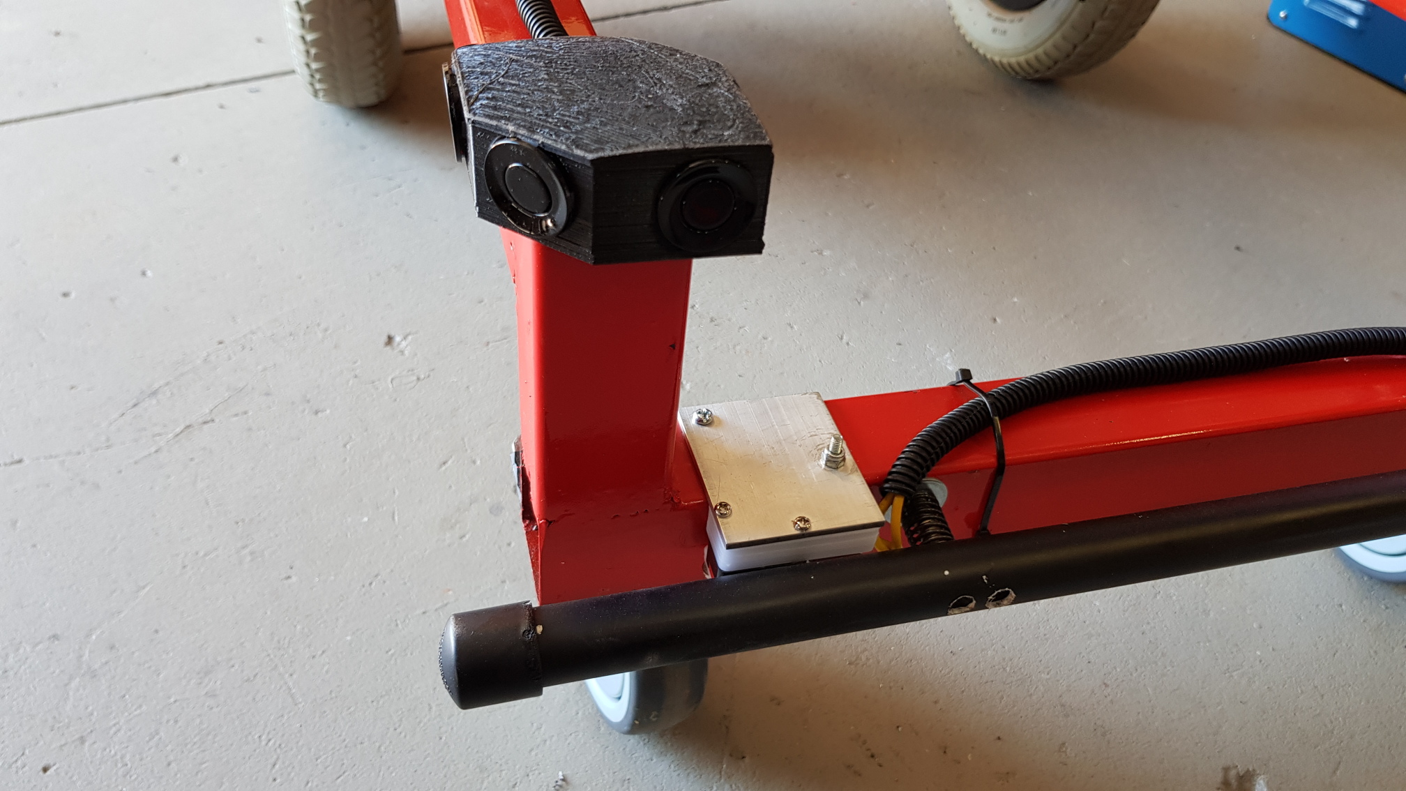 All present, right, diagonal and centre.
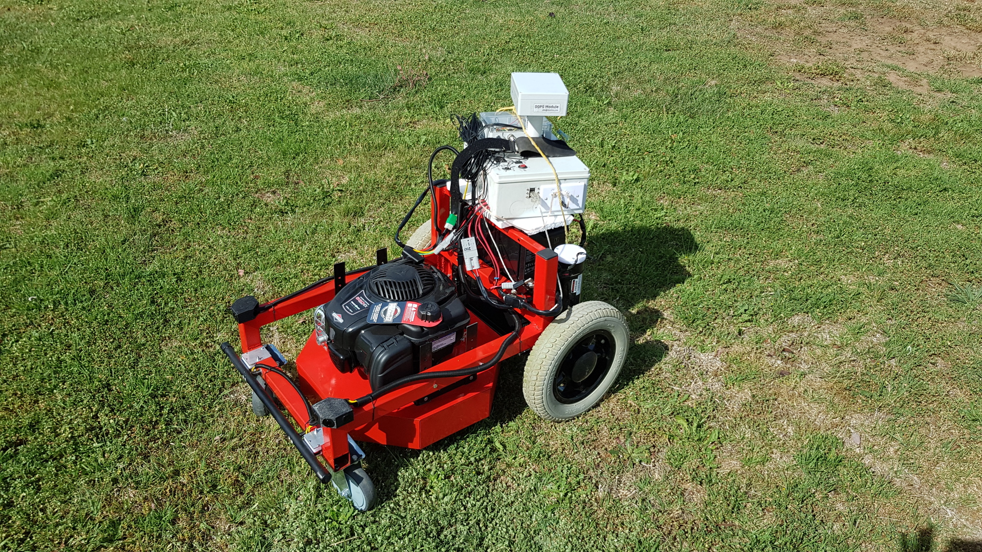 Mow deck mounted.
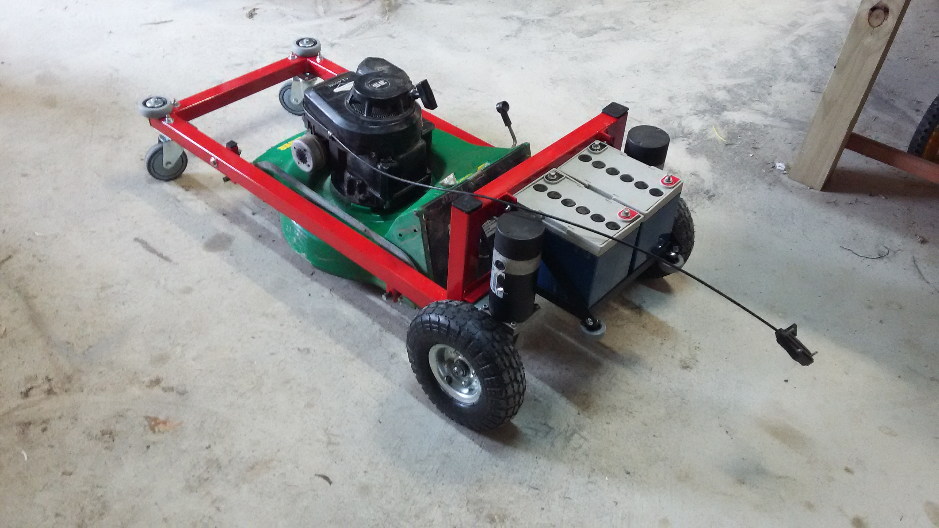
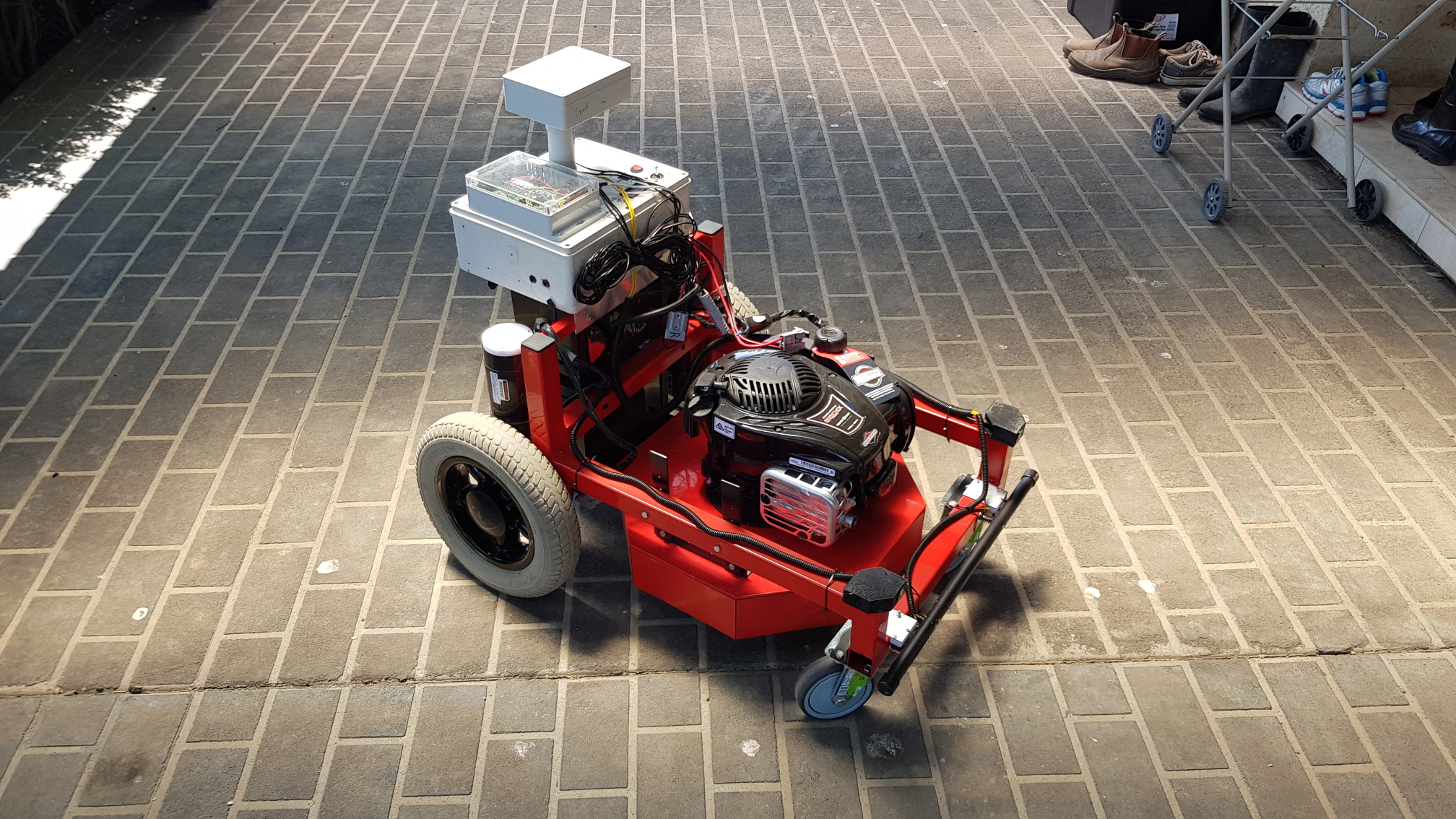
The B&S engine is still untested, but needs to be fitted for testing to provide balance - otherwise the batteries on the back-pack will cause it to overturn.
Yes, the control box is held on with rope here. It was a test.
Circuit diagram
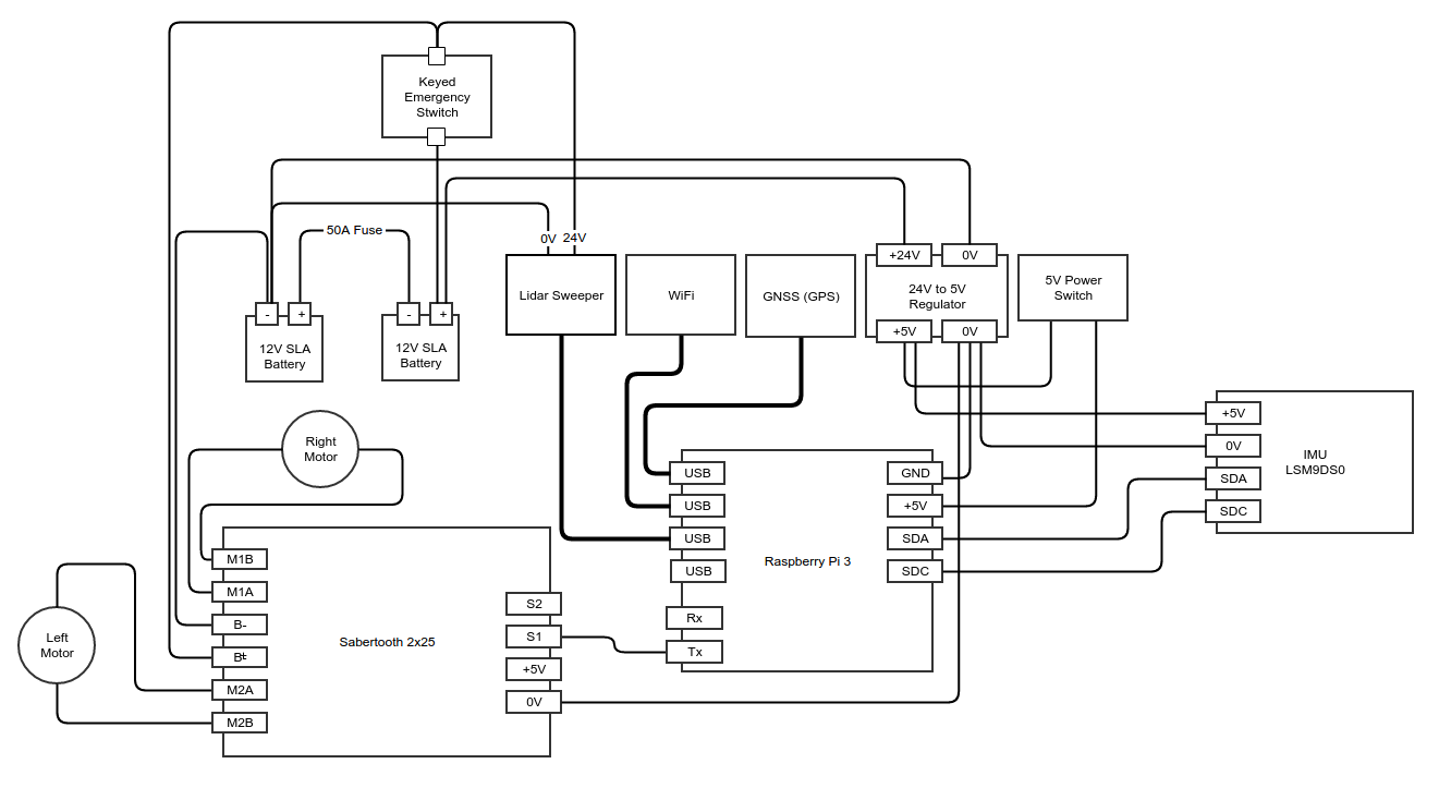
This is the same as the circuit diagram for the Davrover.
Doesn't show the voltmeter to check voltages, or the red flashing strobe light.
Control box
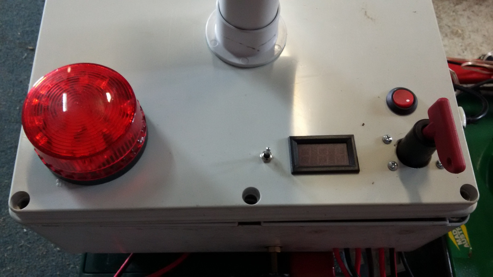
The top of the box
Flashing red light - this is always on when the 24V components are powered.
Two way momentary switch to activate Voltmeter - one way to measure 24V, other way to measure 5V
Voltmeter measures 24V from battery and 5V out from transformer
Small switch 24V, but powering the 24V to 5V transformer
Big on/off keyed switch - high current 24V. This is both a safety switch (with a removable key), and an emergency stop.

Inside the box
Switch-mode transformer 24V to 5V (this has a built-in voltmeter which is not visible when the box is closed). Note that this powers the Raspberry Pi directly through the GPIO. The Raspberry Pi has no over-voltage protection in this mode.
Socket mount for Arduino Nano (not yet actually fitted). This will handle collision detection sensor switches, RPM motor measure, current sensor for electric mower.
Raspberry Pi B Version 3
The Sabertooth 2x25 motor controller. This has been mounted on some flat aluminium with thermally conductive paste to help cooling.
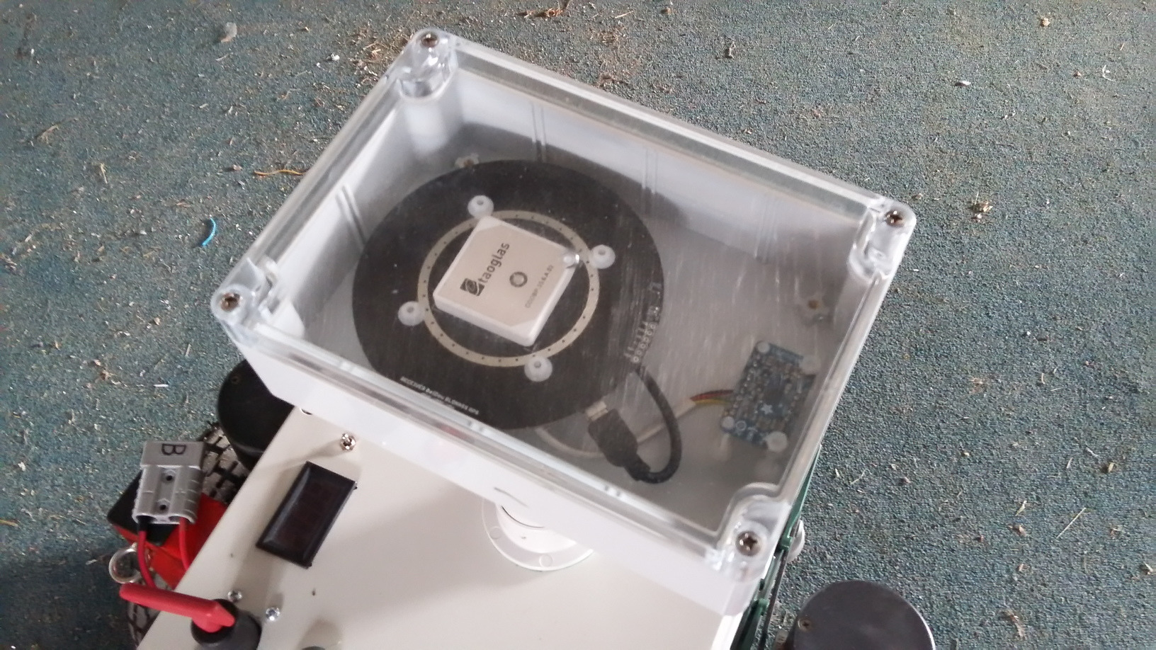
Navigation mast-head
Software libraries

Raspian - Linux for Raspberry Pi
RTKLIB - for the differential GPS
i2c-tools - Raspberry Pi I2C Library
Arduino - for software development on the Nano
Pi4J - Java I2C libraries
Java - for software development.
Software

A truckload of software to make this do anything sensible.
The future

-
Integrating the RPM measurement mechanism. To detect when the mower should slow down because it has hit a thick clump of vegetation.
Throttle control - replacing the governor on the mower with a servo control. This would allow better detection of when the engine was struggling with the vegetation, and when to slow the mower.
Non mowing applications - replacing the mower with other agricultural equipment - weed detection, weed removal, spray boom etc.
Other agricultural uses - replacing the mower deck with other agricultural equipment - weed detection, weed removal, spray boom etc.

Leave a comment
 Something I'm doing wrong? Solved my problems? Got a better idea? Got a similar problem?
Think I might have solved your problem? Ninety-nine problems, but your robot ain't one? Say so ..