Parking Proximity Sensor
Some reverse engineering of a commercial car parking proximity sensor for obstacle detection
Why?

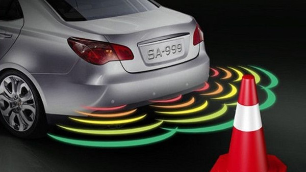
Ultrasonic distance detectors are popular for robotic obstacle avoidance. The detectors squawk like bats, listen for a sound reflection, and compute the distance to an object based on the speed of sound.
Conclusion
This mechanism is an interesting intellectual exercise, but after much experimentation, I question whether it is useful for outdoor robotics.
Parking sensors are designed to assist parking cars, by detecting gutters, walls and other cars - ie large, hard, reasonably flat surfaces, which are ideal for bouncing sound off, and provide an easy-to-detect echo. Sonar devices won't do as well on small or soft objects.
The garden tap might be a single polyethylene pipe sticking out of the ground. There will be very little reflection on that.
A bush or hedge will have soft leaves which absorb the sound or just let it pass through. There will be very little reflection on that.
Indoor surfaces such as walls or furniture might make a sonar approach feasible, but the indoor environment can also work more easily with other solutions like cheap lidar.
Purchase
Unfortunately cheapie sensors such as the HC-04 are indoor-only, as they are not waterproof.
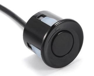
Waterproof sensors do exist. They are have been popular for many years, are used for car parking sensors, have a sensitivity angle of around 90 degrees and are presumably reliable enough to trust for an expensive motor vehicle. They can (supposedly) detect (reasonably large) obstacles within a few meters. They also come in packs of eight sensors - enough for an all-round view for a collision-shy rover.
Unfortunately they are not designed to send the raw distance data to a computer, but are designed to communicate with a dashboard-mounted display device with lots of lights and beeping, and communicate via an unpublished protocol.
There is a unit designed to communicate with a computer via an established protocol - the KS136 Module [Google for "KS136 Ultrasonic Module Ultrasonic Distance Measuring"] can handle 12 sensors simultaneously, but it's obscenely expensive (around eight times the cost of a similar device designed for a car parking sensor), so car parking sensors seem to be a better option, but can the protocol be cracked?
Well, in 2011 a very smart guy called Ishan Karve, reversed engineered a parking sensor and documented his findings for posterity.
Clearly he was much smarter than me so why would I try to emulate his work? Because I had something he didn't. I had his work to copy!
How hard could it be?
Purchase

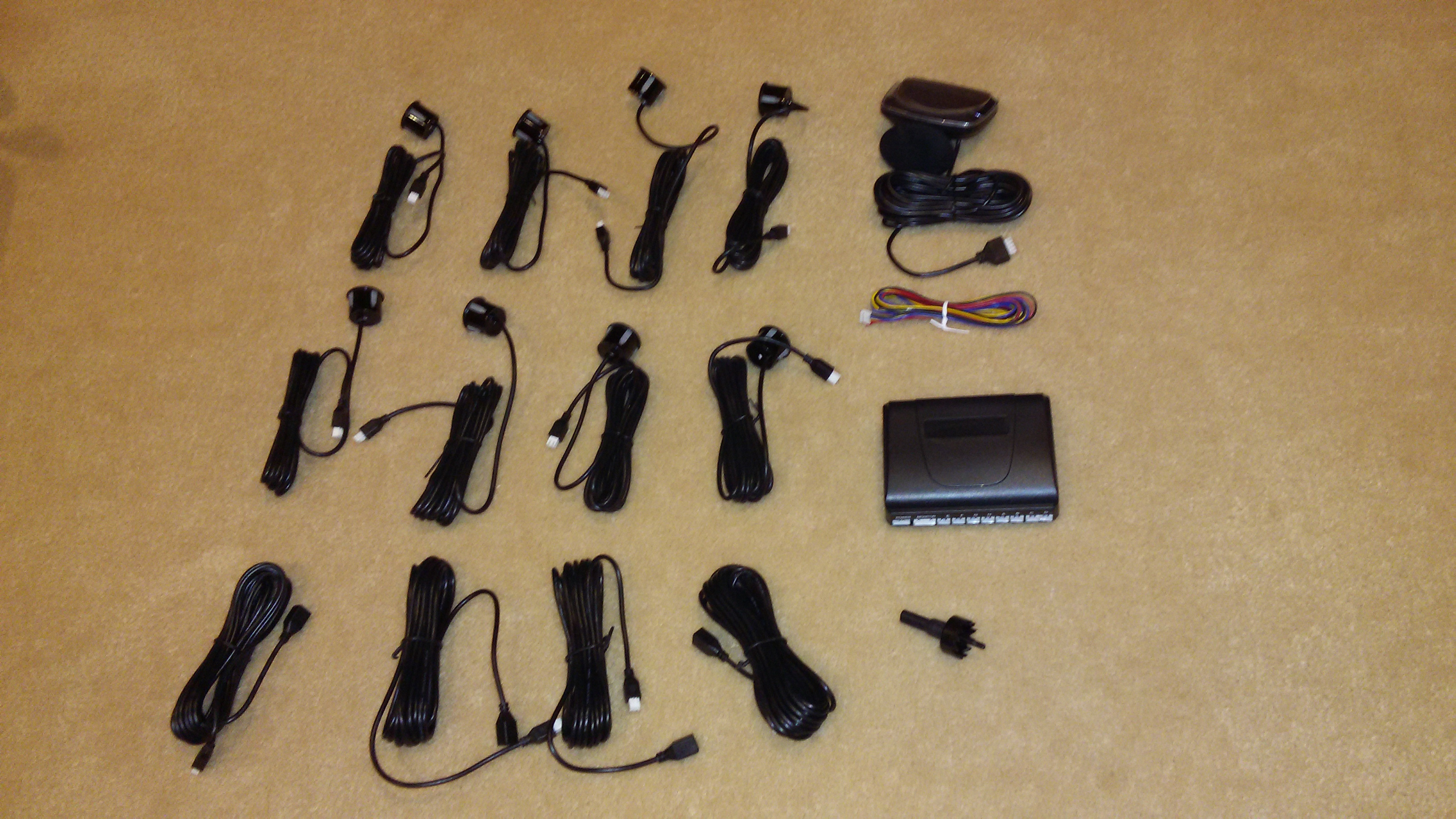
I have purchased two very similar sensor kits. The first, "8 Sensors Wireless Car Reverse Parking Front Rear View Buzzer Alarm LCD Display" kit from boomshakalakatw on eBay, the second "LED Car Reverse Backup Radar 8 Probe 22mm Display 4 Parking Sensors System Kit" from cao-shifen on eBay. The latter is a 'no frills' unit, and was $10 cheaper (spoiler alert: this one is better for robotics).
The former came with some extra bits which were not actually listed - four extension cables for four sensors (presumably the four sensors which are supposed to go on the front bumper of the car).
After plugging everything into a 12V battery to ensure it worked, I unplugged the monitor from the main controller to prod the pins.
Both controllers turned out to be very similar, but the protocol from the controller to the respective displays was very different.
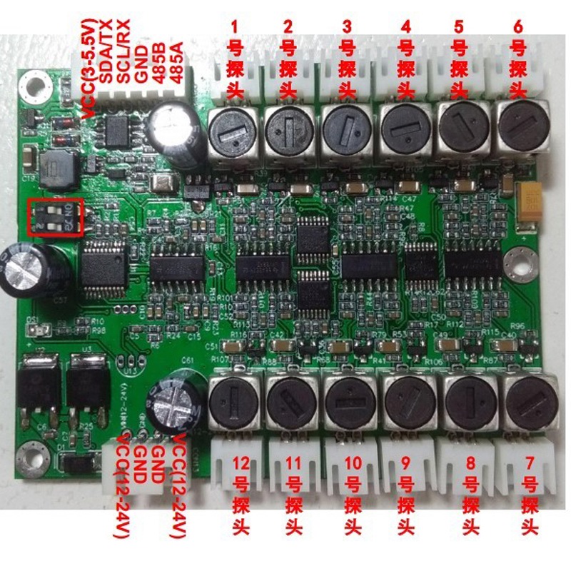
Parking sensor controller
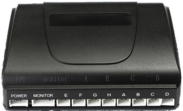
With a bit of prodding with a multi-meter, the pins on the "MONITOR" socket are (from left to right)
GROUND | SIGNAL-OUT | +5V | Who knows |
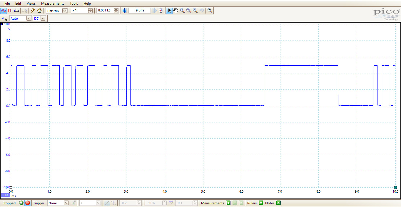
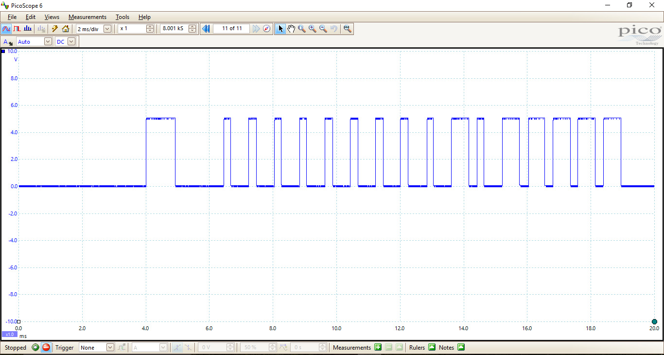
So then it was time to get out the oscilloscope. A bottom-of-the-range Picoscope is great for these sorts of things.
The signal - Controller 1

This is the signal from GROUND and SIGNAL-OUT. The long gap suggests a break between packets, and a start-block:
- 3500us LOW
- 2000us HIGH
- 1000us LOW
The second sample is the start of a packet. Note that the falling edges within the packet body are all equidistant. This seems to be PWM with a 33%/66% duty cycle, 13 falls in 4 ms, ie 300us per bit, ie 3 * 100us. Some further investigation reveals grouping into 48-bit (ie 6-byte) frames.
The signal - Controller 2
 In this case the there is also a gap between packets, followed by a start-block:
- LOW
- 1000us HIGH
- 1250us LOW
Note that the rising edges within the packet body are all equidistant. This seems to be PWM with a 33%/66% duty cycle, 800us per bit, ie 3 * 266us, grouped into 16-bit (ie 2-byte) frames.
Making sense of the protocol
A bit of background is necessary here to make sense of the data.
Even though it is sold as an 8-bit sensor, only four or six sensors actually work at the same time. They are meant to be mounted on the car this way:
              E--F--G--H   Front
              |        |
              |        |
              |        |
              |        |
              |        |
              |        |
              A--B--C--D   Back
If this scheme seems odd, remember that you can get "4 sensor reversing" kits which only have {A,B,C,D}.
There are three modes of the controller, lets call them driving, reversing and braking. Let's think about the how the controller works in a car for a moment.
- When driving along, the system should be de-activated to avoid false alarms etc. This is driving mode.
- When moving forwards slowly (in an automatic), the brake is on (but slipping slowly). Only the front-facing sensors {E, F, G, H} should be active. This is braking mode.
- When backing slowly, the car is in reverse. All back-facing sensors {A, B, C, D} should be on, but only the corner front sensors {E, H} should be active. This is reversing mode.
The designer's intention is that black go to GND, red to +12V, the yellow wire is connected to the reversing light, and the blue wire is connected to the brake light. The controller uses the following logic to determine which mode it should be in.
| BLACK | RED | YELLOW | BLUE | MODE |
|---|---|---|---|---|
| 0V | 12V | 0V | 0V | driving |
| 0V | 12V | 12V | 0V | reversing |
| 0V | 12V | 0V | 12V | braking |
| 0V | 12V | 12V | 12V | reversing |
The easiest thing is to just attach BLACK to GND and the other wires to +12V.
It is frustrating that all eight sensors will not work at a time, but this has advantages for a parking car. The sensors can only be operated serially to avoid hearing each other's pings, and there must be sufficient time between pings to eliminate ringing (in a situation like concrete garage, pings could ring around for quite some time). Reducing the number of operating sensors means that they can be cycled more frequently, and improve response - even 100ms could easily mean the difference between a hit and close call.
Protocol - Controller One
In these modes, the bytes in the packet are assigned to the sensors as follows.
| BYTE NUMBER | |||||||
|---|---|---|---|---|---|---|---|
| 1 | 2 | 3 | 4 | 5 | 6 | ||
| MODE | driving | - | - | - | - | - | - |
| reversing | A | B | C | D | E | H | |
| braking | E | F | G | H | - | - | |
When a byte is not assigned to a sensor, it takes the value 0xFA (think 'F- All'). So when only the red (power) line is at 12V, the packet is always "FA FA FA FA FA FA". When only the red (power) and blue (brake) lines are at 12V, the last two bytes are always "FA FA".
When the bytes are assigned to a sensor, the values are as follows.
| BYTE VALUE | MEANING |
|---|---|
| 0xFA | Sensor not active (think 'F- All) |
| 0xF0 | No object detected (think 'Far 0bject') |
| 0x10 | Object detected at more than 160cm (check this!) |
| 0x0F | Object detected between 150 cm and 160 cm |
| 0x0E | Object detected between 140 cm and 150 cm |
| 0x0D | Object detected between 130 cm and 140 cm |
| 0x0C | Object detected between 120 cm and 130 cm |
| 0x0B | Object detected between 110 cm and 120 cm |
| 0x0A | Object detected between 100 cm and 110 cm |
| 0x09 | Object detected between 90 cm and 100 cm |
| 0x08 | Object detected between 80 cm and 90 cm |
| 0x07 | Object detected between 70 cm and 80 cm |
| 0x06 | Object detected between 60 cm and 70 cm |
| 0x05 | Object detected between 50 cm and 60 cm |
| 0x04 | Object detected between 40 cm and 50 cm |
| 0x03 | Object detected between 30 cm and 40 cm |
| 0x00 | Object detected between 0 cm and 30 cm |
For Example
If the red and yellow wires are at +12V, the packet might be
F0 0D 0D F0 00 0DMeaning that no obstacles were detected for sensors A and D, obstacles were close for sensor E, and medium close (130-140cm) for sensors B, C and H.
Protocol - Controller Two
Each 2-byte packet is the distance information for one sensor. In reversing mode, this cycles around the six sensors {A, B, C, D, E, H}. The first byte specifies the sensor, and the second byte is the distance in centimetres.
Actually the bits in the first byte are organised in a funny way - with a left bit, front bit, middle bit, and bits five and six change according to whether an object is detected or not. Best to just ignore those bits.
Arduino Code
 http://github.com/allegrobotics/arduino parkingsensor1: Arduino code for controller type one (the one with the fancy screen).
http://github.com/allegrobotics/arduino parkingsensor2: Arduino code for controller type two (with no-frills display).
Clearly the type two is actually preferable because it gives range to the nearest cm, whereas the former only gives it to the nearest 10cm. Also the 80cm limit doesn't seem to exist.
Issues

The six-sensors-at-time (and the type-one-only-to-80cm-for-forwards) are disappointing, but can be worked around. There are several configuration possibilities:
Use them as they are designed to be used - four front, four rear, and change modes when the rover changes direction. This would be good for an Ackermann drive rover, but not so good for a differential drive rover - When one wheel is going forwards, and one backwards - and the rover is effectively spinning on the spot - should the sensors being in forward mode or reversing mode?
Use them as they are designed to be used - but put the two middle-forward sensors on the back (facing backwards), put the back corner sensors on the front pointing sideways, the the front middle two facing forward, and the front corner ones at the front, facing at 45°. This is a better fit for a differential drive vehicle, which is likely to be moving backwards slowly. 'Reverse mode' could be activated iff either of the wheels was going backwards at more that twice the speed that another was going forward. [To Do: explain this better - it's a good idea for making a highly manoeuvrable in tight spots vehicle. Later].
Constantly switch rapidly between reversing and braking mode, effectively using all eight sensors. This is problematic for several reasons. One is that it involves switching 12V (on the yellow wire), which is doable, but messy from an Arduino (partly because Arduino is 5V, and also for type one, how long do you wait before assuming that the new data is for the new mode?). The other is that the system seems to glitch a little when the mode is changed - though this could possibly be controlled by having the Arduino carefully control when the change occurs.
Use two parking sensor kits, making a total of twelve sensors. This could actually be done with a single Arduino, with a bit of clever programming, but the sensors might interact with each other and hear each other's pings - so this might not work so well, or might require some careful distancing or sound damping.
To only use 'reversing' mode and hence only use six sensors (and if using a type one controller, use four for long range, two for short range).
A six-sensor detector with two less-sensitive sensors seems a workable compromise. The 'low sensitive' ones would probably be placed at the rear of the rover, with the expectation that reversing would be done more slowly than going forwards. In this way, special programming to know about the distance limitations could be avoided.
Thinking inside the box

A well chosen box this time. Cutting the slits in the front for the cables was gruesome because the box is too big to fit into the CNC, so can't easily be automatically cut. There must be an easier way. Going from left to right, the cables are
-
USB cable from the host (RPi) to the Arduino Nano. This also powers the Arduino.
The 12V power supply to the parking sensor controller.
Wires to the sensors - E, H, A, B, C, D, (G and F are unused, hence the gap in the slits).
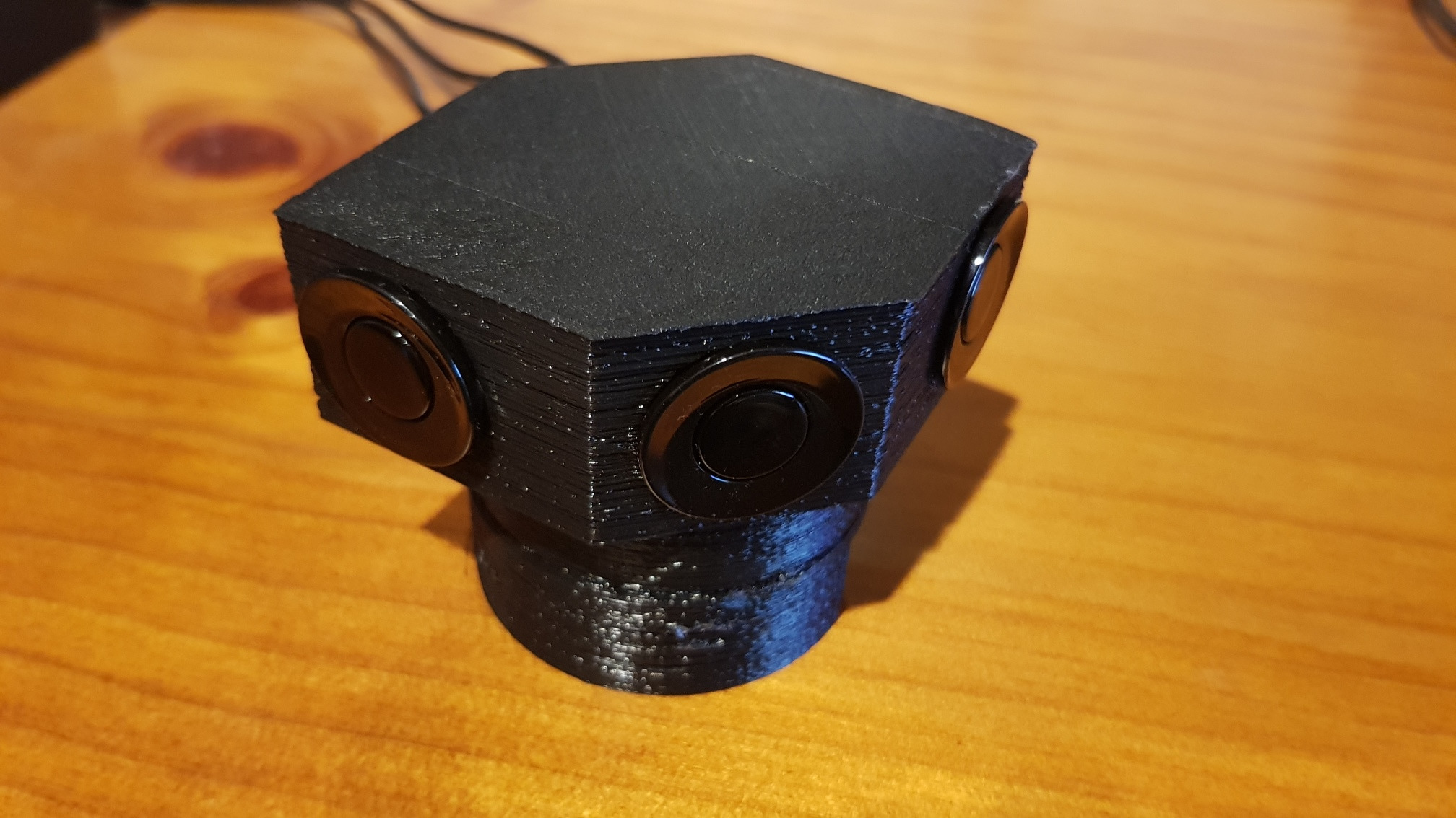
Optimum sensor placement

Six sensors with a field of 90° might sound like more than enough for 360° coverage, but life is not that simple. Firstly coverage at 90° will not be complete (it will be marginal at the edges), and maximum range is not much more than a full rover - the sensors must be placed at the rover extremities to be useful.
Here is one possible sensor placement on a large rover.
The System
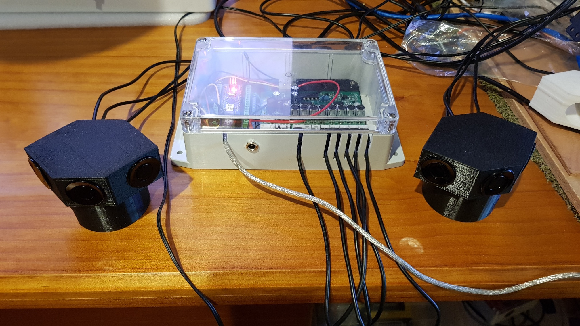
There are two changes that should be made:
Exchange the clear lid for an opaque one - no point in encouraging green-house effect.
Put the parking controller PCB back into its original box (within the new box) because the box it comes in provides support for the plugs, which can easily bend out of shape if the cables are tugged in this arrangement (which might happen in a collision).
Mounted on the Davrover
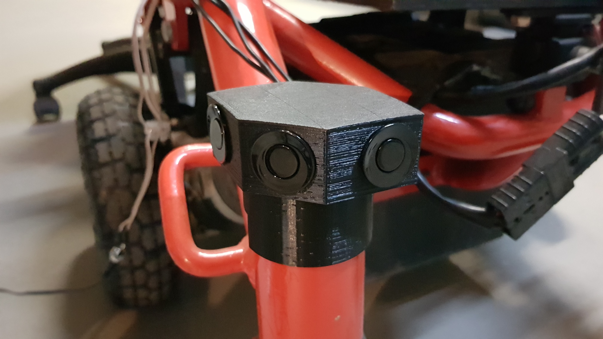
Here are the (black) 3D printed mounts on the front on the rover.
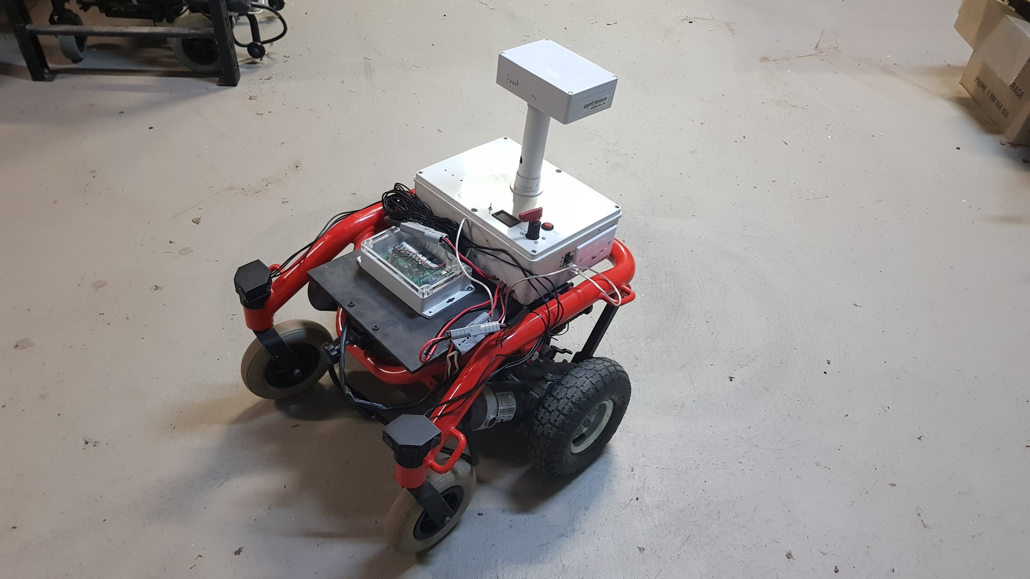
Experimenting with a tamer and less dangerous rover is attractive.
Software

.
Conclusion

These sensors are designed to be fitted to cars to enable them to measure distance to walls, barriers, gutters and other cars. They do not work well on
- sound absorbent materials (which clearly do not reflect the emitted sound). Detecting bushes, trees, or the contents of mum's flower bed might be an issues here.
- small objects (which clearly will not reflect enough of the emitted sound). Detecting the tap in the middle of the yard might be a challenge.
- pathological shapes. Consider a rover approaching the corner of your house - the corner will behave like a stealth fighter - the sound will be reflected by each wall, but away from the source. The rover is unlikely to detect it.
Cool links

-
Get Allegrobotics updates on twitter
Inspiration for this project was from work done by work done in 2011 by Ishan Karve. I owe him a beer.
Instructables: Hacking Automotive Ultrasonic Sensors. For the really adventurous.
Leave a comment
 Something I'm doing wrong? Solved my problems? Got a better idea? Got a similar problem?
Think I might have solved your problem? Ninety-nine problems, but your robot ain't one? Say so ..