MachisMow
Conversion of ride-on lawn mower to autonomous farm slasher
Don't try this at home
Warning: Don't try this at home unless your home is on many acres of fenced off area. This robot is about as dangerous as agricultural machinery gets. It is not a cute project to work on with the kids. It is 200kg of unforgiving metal powered by 20 horsepower of searing hot engine, with heavy machete-style blades spinning at around 200km/hr. Also, zero-turn / differential drive is much more dangerous than a 'normally steered' rover because it can go in any direction very quickly.
Think for a moment about what would happen if you get forward and backwards mixed up on one side or even just got left and right mixed up, and the the mower just started spinning wildly, and ignored the remote control cut-out. How could it be stopped?
Anyone thinking of building this kind of robot needs to think these issues through very seriously. And if you are not wearing steel-capped boots you are playing Russian Roulette with your toes.

Motivation

Anyone with an old zero-turn ride-on mower lying around probably wishes they didn't have to actually drive it themselves.
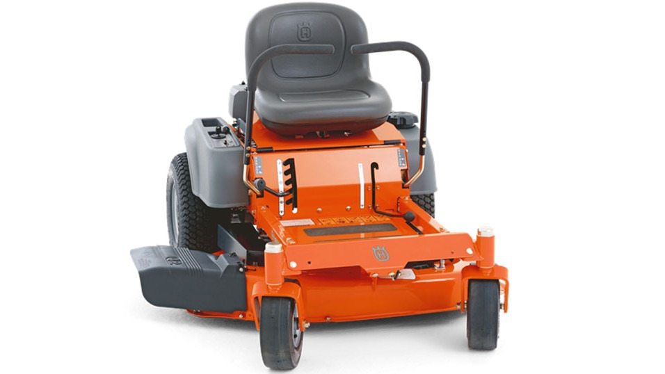
This is a Husqvarna RZ4221, a 'zero-turn' mower which uses a differential drive system - ie the same wheel configuration as the rest of the robots. Automating a ride-on mower can be done by replacing the motion control levers with linear actuators to operate the the 'engage' push-rods into the gearbox.
Further the modifications should be possible without making any irreversible changes to the mower - which is desirable firstly because it is serviced annually by the mower shop, who might the refuse to service it if they are confused about the modifications and secondly because the mower can be reassembled and sold as a normal mower - unused ride-on lawnmowers are expensive accessories.
This mower has had the seat removed to allow access to the internals. The mower deck has been temporarily removed to make it lighter and safer during testing.
Assembly
There are three main mechanical parts to this project.
- Control of the movement - mechanising the control levers
- Replacement of the mower electrical system - controlling the engine
- Collision detection via tripwire
Mechanising the control levers
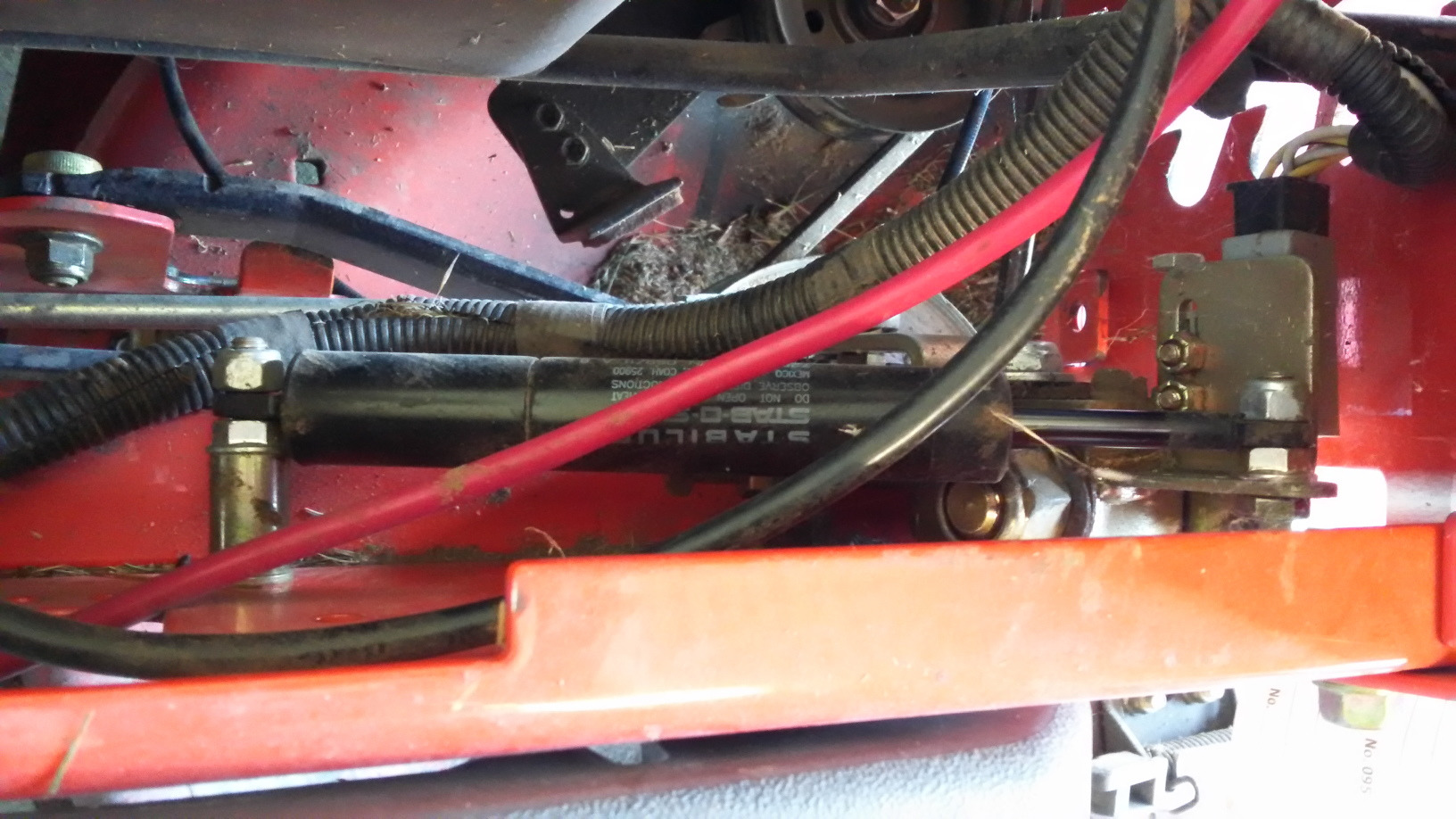
It's a little hard to see in the clutter, but the black cylinder in this picture moves in and out when the motion control lever is moved by the driver. There is one on each lever. They are designed to slow the movement of the motion control levers to discourage the driver from 'dropping the clutch' (which both knocks the equipment around and tears up the grass). These have about 30mm of travel - stopped=195mm; full-reverse=185mm; full-forward=215mm.
Below the damper cylinder (even harder to see) is a push-rod (going off to the left) which goes into the gear-box, and engages drive to the wheels.
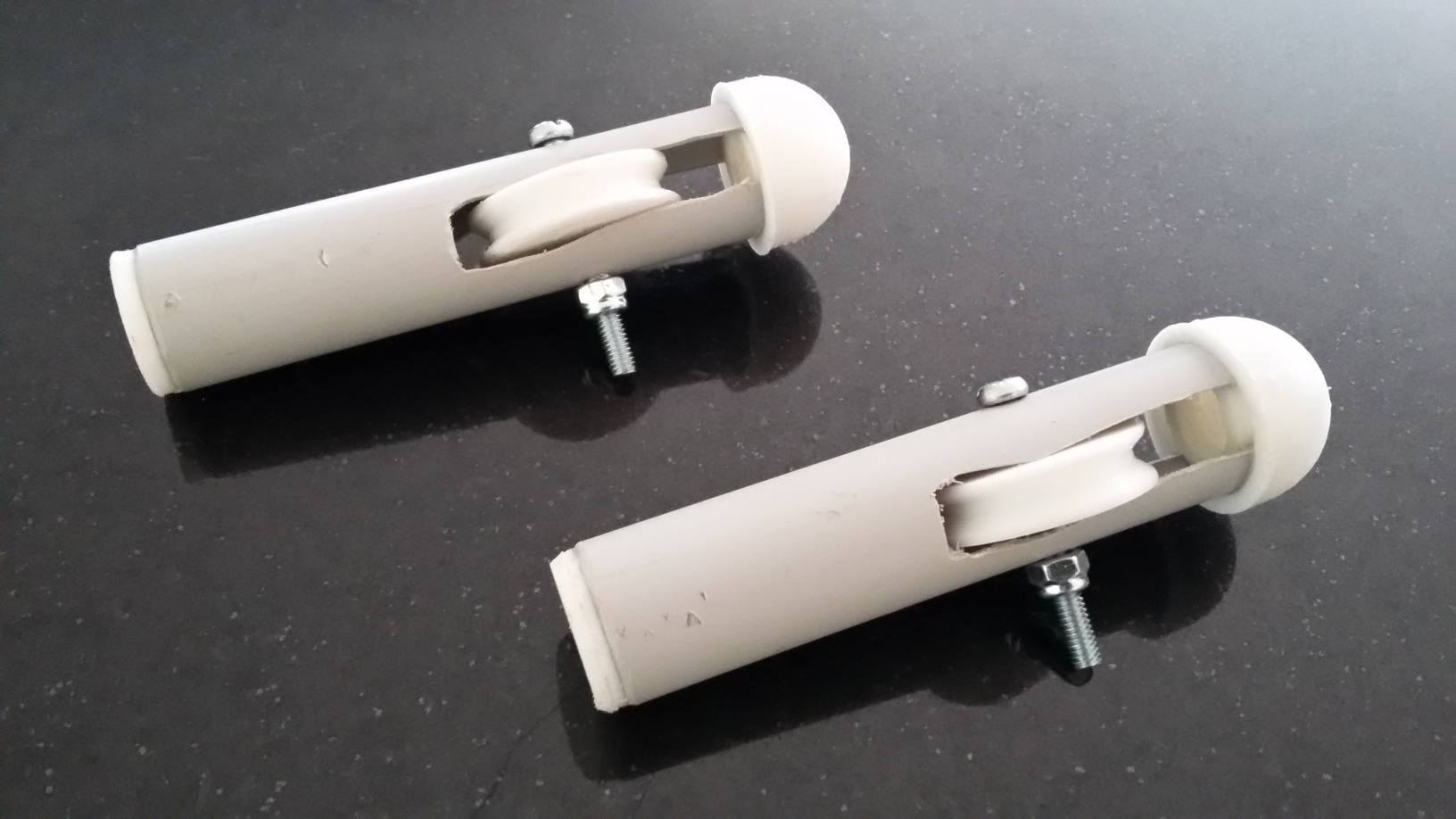
Linear actuators
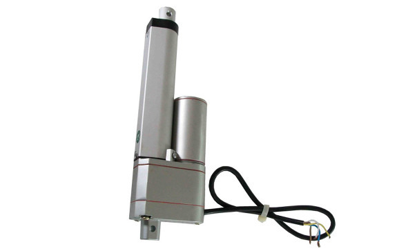
This is a 50mm linear actuator with 10K feedback potentiometer for positioning feedback, and the potentiometer wiper can be connected to an Arduino analog-in pin. (Strangely, the actuators seem to get much more expensive when a $1 feedback pot is added - presumably because they are no longer 'consumer' items).
These actuators are almost the same size as the damper cylinders, so it should be possible to replace the damper cylinder with one of these - we just need to put an extension lever on it to translate the 50mm of travel to 35mm. In principle, we could just use 30mm of the 50mm possible movement, but if the actuator moves outside the range, then the system must be designed as to not cause damage.
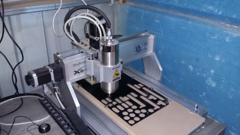
Actuator levers - made with a CNC
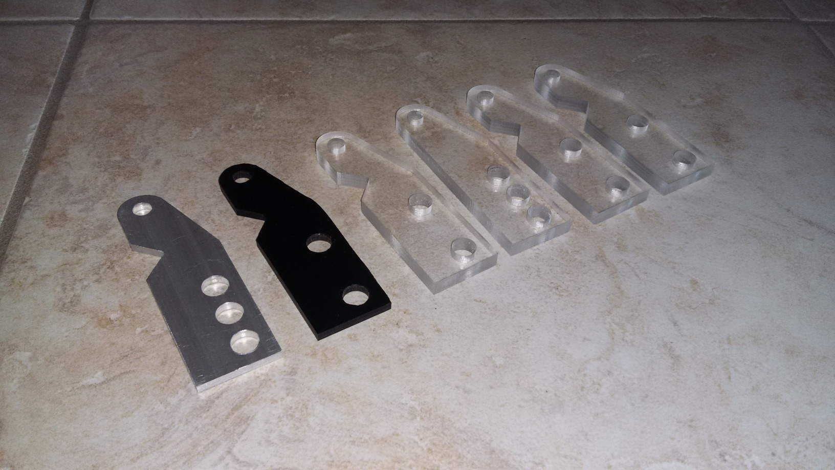
The space in the mower is pretty tight, and the levers have to be quite a distinct shape to make everything fit. These were designed with openscad and cut out on a CNC. We only need two of these, but these were experimental. 6mm perspex was chosen as a good trade-off between strength and ease of milling.
Actually a CNC is overkill for this - a hacksaw, drill and file would be effective here.
Replaced

Here the control levers have been removed, and the damper cylinders replaced with the actuators. It's a little hard to see all the components, but the actuator is connected to the perspex lever, which extends the existing lever (we have to accommodate 50mm of play instead of 35mm with the damper piston). This rotates about the large bolt below it, and below that the lever is connected to the push-rod, going back into the gear-box.
Unfortunately this arrangement means that there is no longer any visual indication of where the neutral point is (ie the 'mid-point' at which the wheels move neither forwards or backwards). Hence calibrating the actuators is going to tricky and potentially dangerous.
In the end, this was done by lifting the the mower into blocks so the drive wheels could spin freely, and using the manual control to move the actuators until the wheels stopped. Marks were made on the actuators at the neutral point so that the software could be calibrated with the mower turned off.
Replacement of the electrical system

Re-wiring the RZ4221
Clearly the wiring needs to be modified to interact with the controller. The mower has a wiring harness which interacts with the brake, seat switch, control levers and blade engage in complicated ways to cut out the engine if something unexpected happens. There are basically two approaches to this.
- Fake it: build another harness to plug into the existing one which effectively replaces the switches with relays, activated to satisfy the harness logic that everything is safe and normal; or
- Replace: Bypass the wiring harness and just control the motor directly with some custom circuitry.
Faking it is quite complex - powering the motor directly is much simpler.
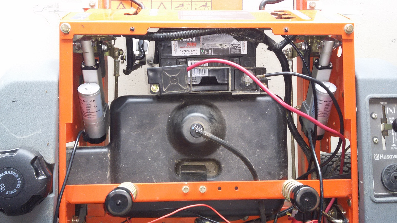
Replacing the harness and powering the motor directly
There are three wires into the motor (apart from the ground / 0V wire), a red wire, a black wire and a gray wire.
- When the engine is running, the red wire and gray wires should be connected to the (+12V) battery anode, and the black wire should float.
- To kill the motor, the black wire should be held to GND / 0V / battery cathode.
So a latching relay should keep the black wire floating, and trip it to ground to stop the motor, or it should de-latch when something goes wrong like
- Collision detection: like a tripwire being tugged. This should be on a latched relay directly breaking the ignition circuit - that is, is should by-pass the software completely.
- Excessive tilt: this would indicate that the rover had capsized or was doing something silly like climbing the dam wall, a fence, tree or a building.
- Unfed watchdog: some critical software process(es) no longer running (or running too slowly).
- Emergency stop button pressed by a human supervisor.
Drive model
While the logic of the differential drive is similar as the other robots - in practice there is a significant difference. While previously, driving the wheels has been programmable with a 'drive motor at power X', this would require a 'move actuator to position Y to achieve drive motor power X' paradigm. And there are no position encoders. This is not actually a complicated change (it's just a few lines of code), but has safety implications.
- Full rated speed of the mower is around 10km/hr (3.6m/s).
- The actuator has a speed of 40mm/s (a little less when loaded).
- Moving from full speed (forward) to stop will be a 20mm movement, and will require 0.5s to achieve.
- We can expect the mower to move around
s = ½at2 = 0.9min this time.
Manual test controller
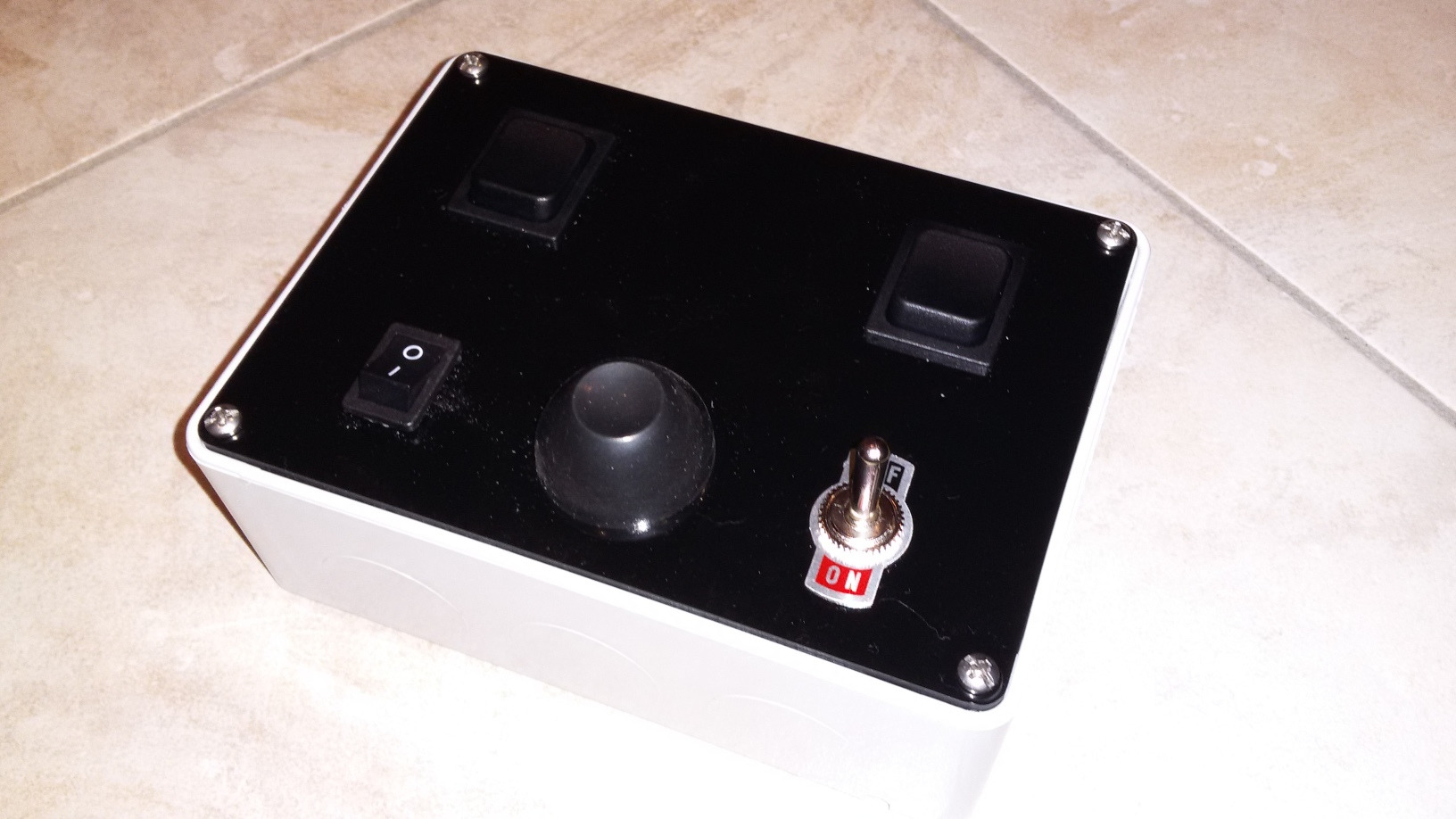
This test box is for manually controlling the unit without a computer. It tests the actuators, and also the electrical system to the motor. It is a project box, with the lid replaced with a control plate cut out of a sheet of 3mm acrylic with a CNC. There are two two-way toggle switches to control the actuators. On reflection (excuse the pun), black was not the best colour for the acrylic sheet, but I used what I had. There is an ignition switch on the bottom left, a kill switch on the bottom right, and a motor-start button centre-bottom.
Even being operated with this control box the machine is quite dangerous - moving the toggle switches back to zero will not stop the machine, but simply leave it moving (or turning) at the same rate. Stopping the machine actually involves moving both actuators back to the zero position. Or emergency-stalling the machine.
Autonomous control box
The electronics was mounted in a plastic project box, and this was mounted where the seat used to be.
The base of the box is black acrylic, which turned out to be a very poor choice as it maximises the greenhouse effect with the clear top.
The start-up procedure is as follows.
- Main switch is turned on. This starts the Arduino, which flashes the strobe "1, 2" which is "ready for start-up test", and also boots the Raspberry Pi.
- Voltages are checked - 12V and 5V.
- Actuator Test momentary button is pressed, which moves the actuators, and ensures the position feedback is working. Checking that left/right are not swapped and forward/back are not swapped is done by the operator.
- At this point the remote control unit can be used to move the actuators.
- The ignition latching relay is enabled - the Ignition Latch momentary button is pressed, latches the ignition relay.
- Throttle is moved to 'choke' (starting position).
- Starter motor is pressed, which engages the starter solenoid, and runs the starter motor.
- When the engine is running, the throttle is moved to 'run'.
- The engine can be killed by pressing the emergency stop button or pressing stop on the remote control or by tripping the collision detect. Any of these actions unlatch the ignition relay, stopping the motor.
Tethered test
Testing whether wheels actually spin - while rover is off the ground, and also suspended off a crane in case it decided it wanted to explore the workshop.
Collision detection via tripwire
A little trick I picked up from watching videos of SwarmFarm Robotics videos. Those guys rock.
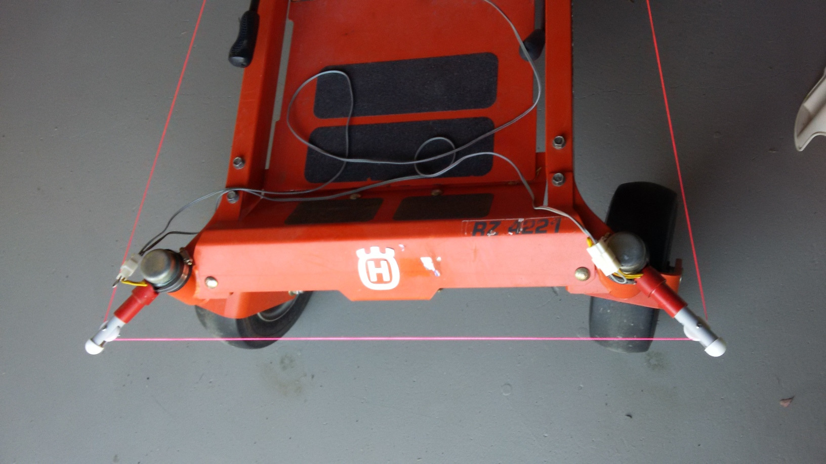
Ideally all sides of the mower should be covered, but as the unit never goes backward (by the current design), protecting the front should be sufficient. The biggest risks are
- running over something when travelling (more or less forward), and
- having the whole mower spin (opposite wheels go to maximum in opposite directions simultaneously), making it very hard to jump on and press the emergency stop button.
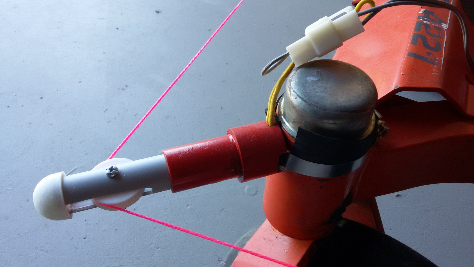
Collision detection bumper
 .. an alternative
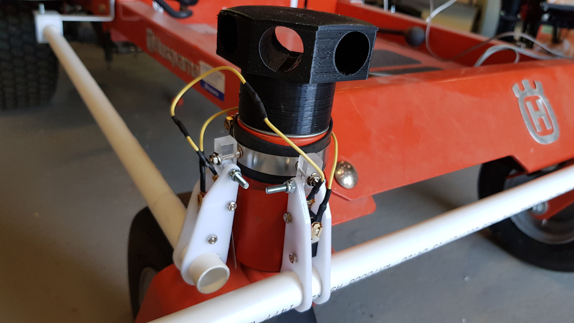 Parking sensors have not been fitted to the holder yet.
First run
Yes, it actually works - as a remote controlled vehicle anyway. This is not yet autonomous.
- The IMU/DGPS box is not yet fitted, nor is the lidar sweeper. This is just a test of the mobility and safety shutoff.
Direction test
Testing the IMU - compass. A simple program to point north/south/east/west.
- The IMU and DGPS box is now fitted but not the lidar sweeper. This test is autonomous, but just changes the orientation of the rover- effectively a test of the compass and steering algorithms.
- The final directions are not very accurate - the system deliberately has large dead-zones and slop so these can be tightened up later. Over-constraining these too early is likely to stress the actuators - which are only rated to a 50% duty cycle.
Path following field trial
Making the rover follow a pre-programmed way-point course in the paddock.
- Out in the fields, following a rectangular way-point around the paddock. The DGPS and compass (IMU) are used to navigate around the paddock.
- Next step: Tighten up the steering parameters (to reduce the 'wander').
- And then: Collision avoidance, either the lidar sweeper or the ultrasonic parking sensors.
Issues and non-issues

There is no need to replace the throttle with an actuator. The glory of lawn-mowers, they have a governor, which can simply be set manually.
The mower is much lower without a seat or an operator. This means the mower can go under trees and bushes - though this creates navigation and collision issues.
Computing hardware

Medulla: an Arduino is used to just control the actuators for the control levers. There are many reasons for this - if the main computer crashes, the Arduino can trip the emergency stop button and also bring the actuators to the stationary position. Also, the Raspberry Pi is very susceptible to crashing with unstable voltage supply, the Arduino is considerably more robust, but not sophisticated enough for the navigation and decision making.
Software

Pretty much the same software as the GizMow except with a larger wheel-base, wheel-size and rover-length.
An extra class can convert drive motor goals to Arduino actuator commands.
Also, the mowing algorithm.
Cool links

-
Get Allegrobotics updates on twitter
The Manscraper.
Others doing some cool stuff.
Others doing some Mowbotics.
YouTube video of remote controlled ride-on mower.
Greenzie use stand-on mowers for their conversions. Very cool. Directed Machines. Check out their YouTube Channel. Bitdog on YouTube - automation of the Evatech Goat 22 RC
Leave a comment
 Something I'm doing wrong? Solved my problems? Got a better idea? Got a similar problem?
Think I might have solved your problem? Ninety-nine problems, but your robot ain't one? Say so ..