Skidrover
You don't worry about skid-marks when you are on Skidrover.
WIP warning
Why?

The issues with skid-steer vehicles in agricultural settings are well known. However light, small vehicles employing skid-steer are useful for navigation and data-gathering tasks. Hoverboard in-wheel motors make excellent motors for a project like this so .. why not?
Working plan
Buy two second-hand hoverboards.
Strip out the four wheel-motors and the two control boards.
Re-program the mainboard chips.
Mount them into a custom build skid-steer rover, and control both motor drivers from an Arduino (or ESP32).
What could possibly go wrong?
Rather a lot actually ..
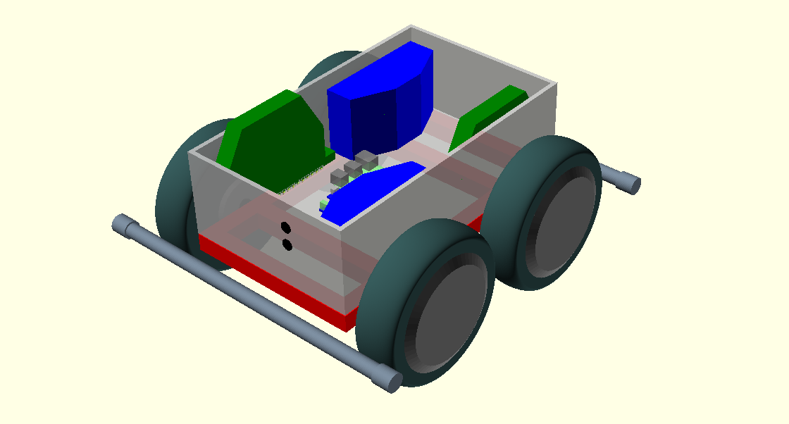
The CAD concept
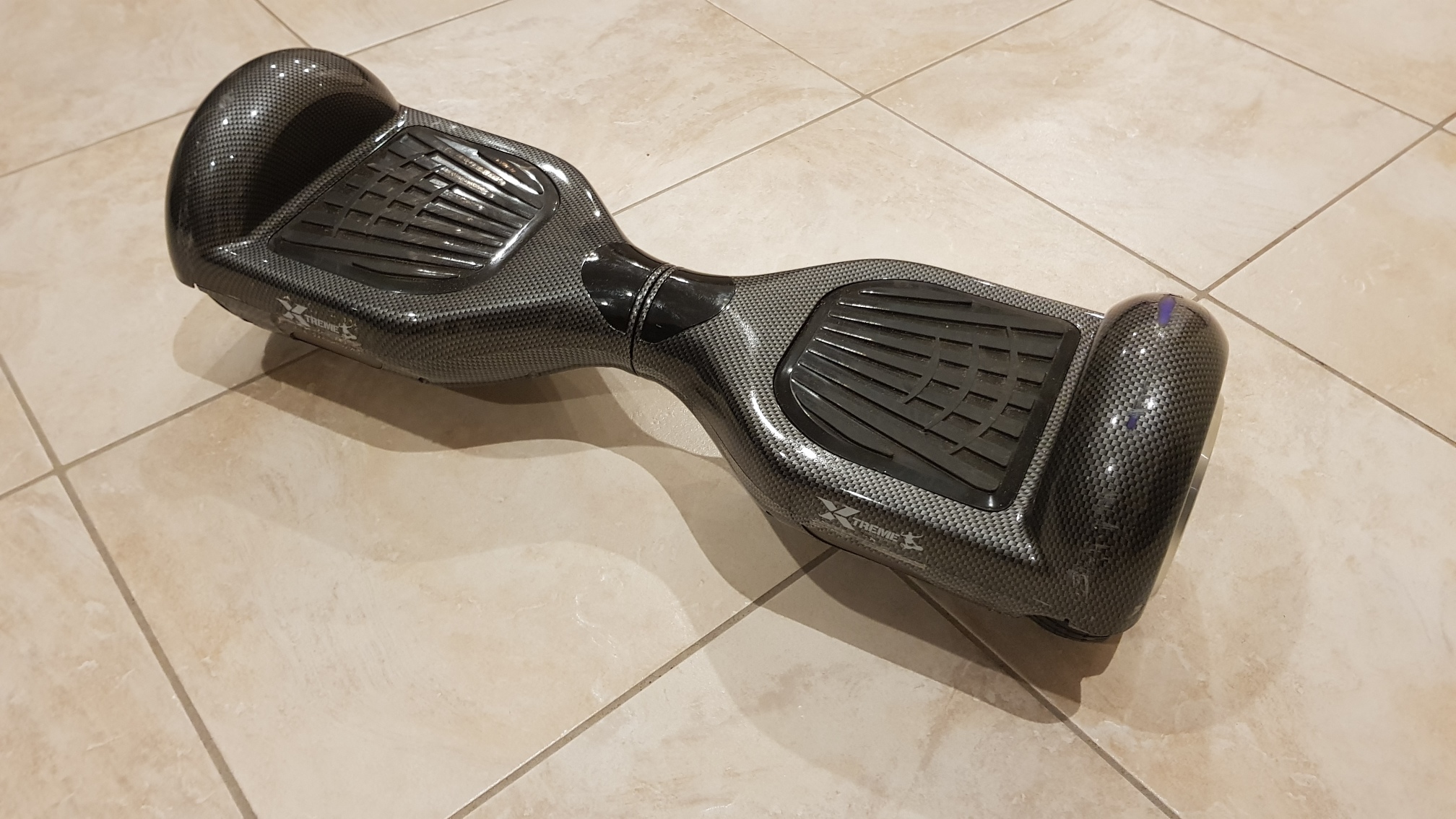
The buy
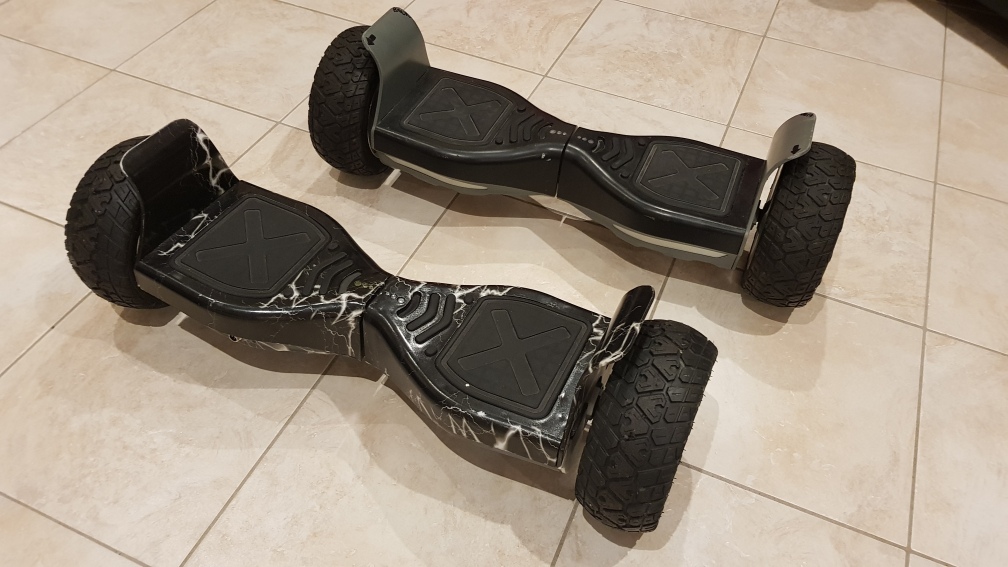
Monster rovers
These bug chunky 'off-road' 8-inch hoverboards are the bomb, but they are much harder to come by, and more expensive than the standard 6.5-inch units.
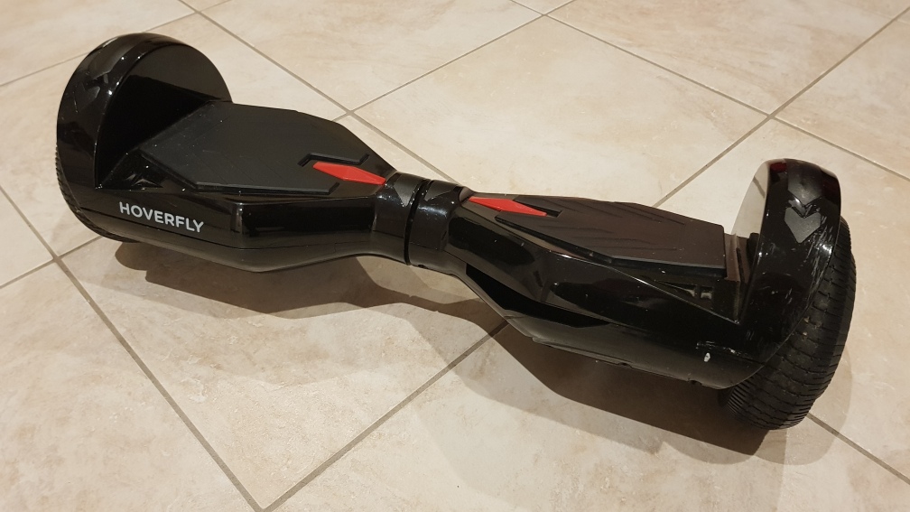
Cheapies
On the other hand, this one is a real cheapie - smaller battery, tiny recharger, and guaranteed to have less power than the others. However they are cheap - and sell for much less than the larger ones. Also, the fact that the body is made of cheap plastic (instead of metal) doesn't really matter if you are going to throw most of it away.
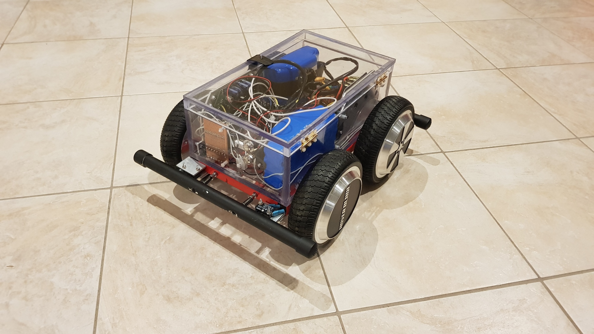
The build
The decision was made to first build a prototype with the parts from the small (6.5-inch) wheel hoverboards, and work up to a more rugged 'around the farm' rover on a second go.
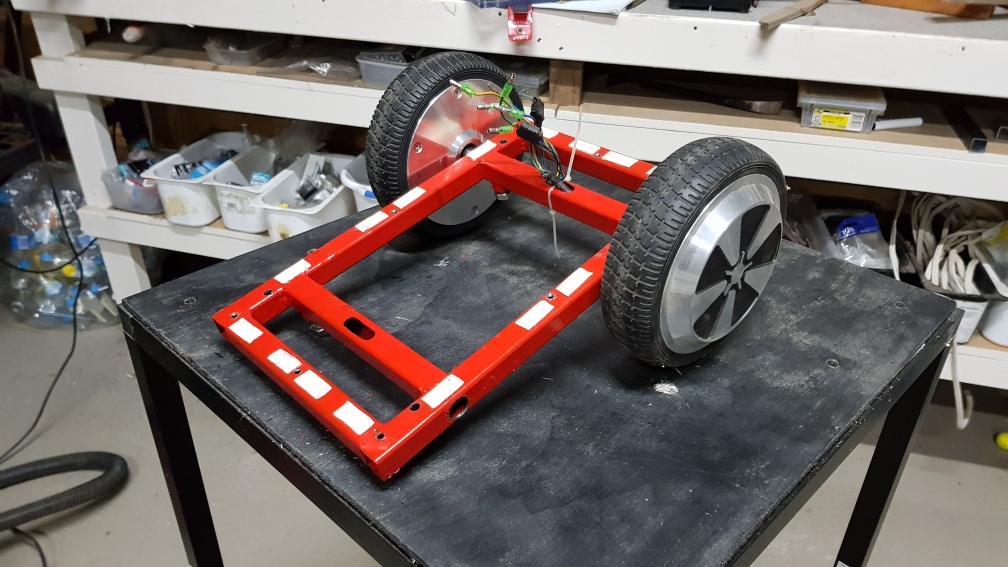
Base
The base is mild steel square tubing 20mm on the outside, with a thickness of 1.6mm. This leaves 16.8mm on the inside, which just fits the 16mm axle of the hoverboard wheels comfortably. A 16mm drill was costly, but a good buy. The base was drilled, welded and very roughly painted (it's only a prototype).
Wheels
The flat of the axle can be held in place by a 10M bolt on the base of the rover, and the wires (which go through the axle can be fed up through a hole in the axle tube. Be warned that this is tighter and messier than it looks.
Be very careful to file the inside edges of the frame as smooth as possible around the middle slit. I stripped a few wires to the metal pulling them through. Embarrassing and messy. Take care.
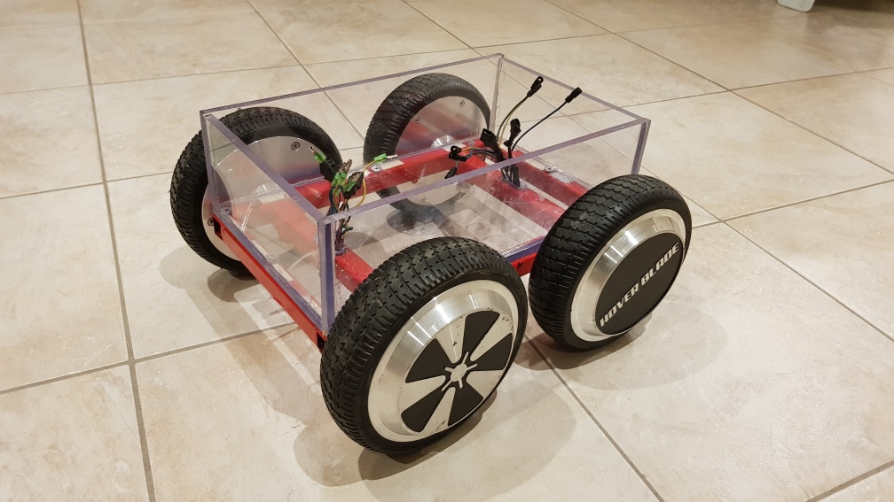
Box
There are many ways to skin a cat-girl robot, but 8mm (clear) perspex worked a treat for this robot. This is quite strong, and 8mm can be easily tapped to make threads to hold components (battery, controller, processor, etc) into the box. Clear perspex also simplifies debugging - it's easy to see which lights are on, or if wires are loose in the box. Unfortunately clear perspex also shows up all of the mistakes, which can normally be quietly concealed with an opaque box. Life is a circuitous learning journey.
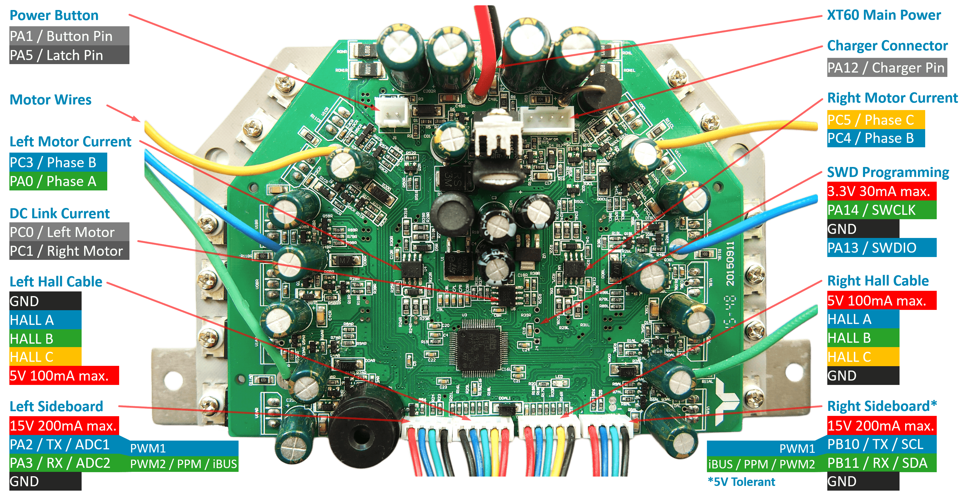
Drivers
Fortunately in my purchases I ended up with two first generation mainboards. One controls the back wheels and one the front. These were reflashed as described on the hoverboard page.
Bumpers
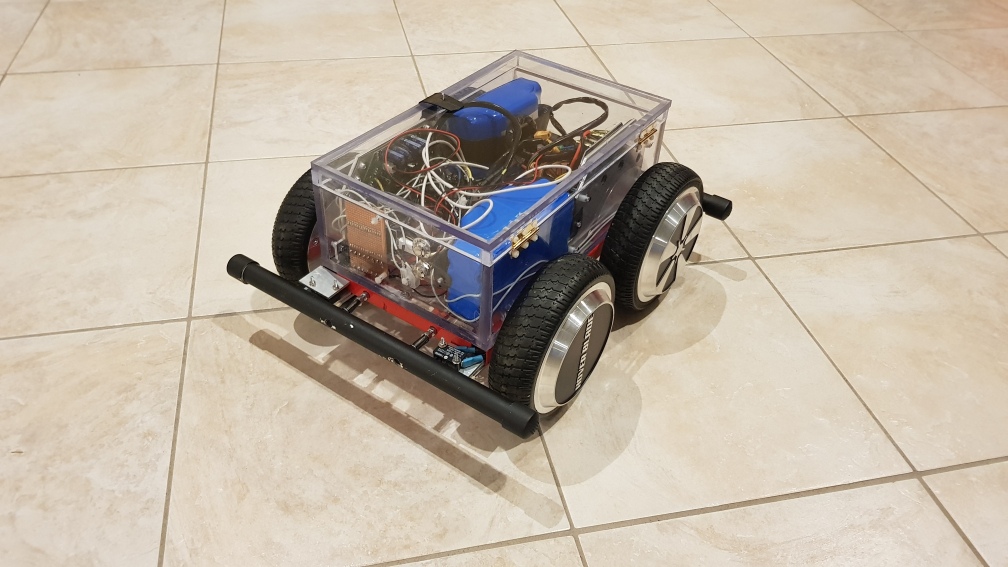
Collision detection can be done with bumpers and micro-switches. Spray-painted PVC pipe is cheap, effective, and may protect the rover in moderate collisions. An appropriately positioned micro-switch at each corner not only allows detection of the most common collisions, but also allows enough feedback to enable some simple collision strategies (eg like backing away from the object). This arrangement also detects if a bumper is caught on something and the rover is trying to pull away from it (though the escape algorithm in this case becomes a little more involved).
This is untested, but the following seems intuitive: If a single corner bumper is in-collision, reverse the wheels on that side, while stopping the wheels on the other. This will reverse out of a simple corner collision, and also tend to drag the rover sideways away from anything catching the bumper on the wrong side. Real-life mileage may vary.
Driver control - the medulla
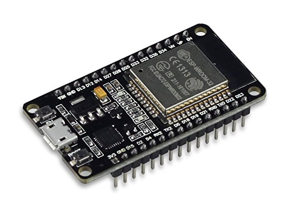
The hoverboard mainboards like to communicate at 115200, but multiple connection will not be sent or received reliably at this speed by bit-bashing a Raspberry Pi. We also need a GPIO to monitor the bumpers and such-like. Normally a cheapie Arduino Nano can be used for these kind of tasks, but it will not handle multiple serial connections reliably. Enter the ESP-32 chip.
The life-support functions can be handled by ESP-WROOM-32 board. These are amazingly fast for the size, power consumption and (best of all) price. These should handle three connections (RX/TX to host, and RX/TXs to both controllers) provided the communications with the hoverboards are slowed from the 115200 to around 19200 baud.
Software

The Hoverboard1G.h / Hoverboard1G.cpp Module in github handles this. This module is tailored to the ESP-WROOM-32 chip, but will probably work with other reasonably fast chips too. The Hoverboard1G module assumes the availability of two HardwareSerial interfaces. Small Arduinos (like the Nano) probably won't support this.
//-*- mode: c -*-
/*
 * NAME
 *     skidrover.ino
 * PURPOSE
 *     Medulla of the skidrover (dual hoverboard wheel drive with corner bumpers).
 *     This controls the most basic low-level functions of the rover.
 * NOTE
 *     UNTESTED AS AT 2022-10-07
 * SEE
 *     http://allegrobotics.com/hoverboard.html
 *     http://allegrobotics.com/skidrover.html
 * COPYRIGHT
 *     Allegrobotics 2022. IP freely on non-commercial applications.
 * PIN ASSIGNMENTS ON ESP-WROOM-32
 *   GND     - GND
 *   D2      - built in LED for feedback
 *   D16/RX2 - to Front hoverboard mainboard
 *   D17/TX2 - to Front hoverboard mainboard
 *   D18     - RX1 to Back hoverboard mainboard
 *   D19     - TX1 to Back hoverboard mainboard
 *   D23     - Bumper FL
 *   D4      - Bumper FR
 *   D21     - Bumper BL
 *   D22     - Bumper BR
 */

#include <Arduino.h>
#include "Application.h"
#include "Blinker.h"
#include "Hoverboard1G.h"
#include "Bumper.h"

#define LED_BUILTIN             2       // The built in LED on the ESP32-WROOM

// Front hoverSerial - user UART2, ie RX2/TX2. D16 and D17 seem to be 'kind of' hardware for UART2
#define HOVERSERIAL_F_RX       16
#define HOVERSERIAL_F_TX       17

// Back hoverSerial - D18 and D19 are just made up, but someone suggested the chip is smart enough to use (almost) any pin pair for UART1
#define HOVERSERIAL_B_RX       18
#define HOVERSERIAL_B_TX       19

// Bumpers - one each corner
// Bumper switches are normally closed, and earthed, so these pins require INPUT_PULLUP.
#define BUMPER_FRONT_LEFT_PIN  23
#define BUMPER_FRONT_RIGHT_PIN  4
#define BUMPER_BACK_LEFT_PIN   21
#define BUMPER_BACK_RIGHT_PIN  22

#define HOVER_SERIAL_BAUD   19200      // Baud rate for communication with hoverboards (note hoverboard must be re-flashed for this speed)

HardwareSerial *frontHoverSerial; // The RX/TX serial connection to the front wheels controller
HardwareSerial *backHoverSerial;  // The RX/TX serial connection to the back wheels controller

Blinker blinker(LED_BUILTIN);
Hoverboard1G frontHoverboard('F', &Serial1, HOVERSERIAL_F_RX, HOVERSERIAL_F_TX, HOVER_SERIAL_BAUD);
Hoverboard1G backHoverboard ('B', &Serial2, HOVERSERIAL_B_RX, HOVERSERIAL_B_TX, HOVER_SERIAL_BAUD);
Bumper bumperFL(BUMPER_FRONT_LEFT_PIN,  '0');
Bumper bumperFR(BUMPER_FRONT_RIGHT_PIN, '1');
Bumper bumperBL(BUMPER_BACK_LEFT_PIN,   '2');
Bumper bumperBR(BUMPER_BACK_RIGHT_PIN,  '3');

void setup() {
    delay(500);
    Application::setup(115200);
    Serial.println("AI Skidrover V1.0");
}

void loop() {
    Application::loop(millis());
}
Issues

Yeah, we all got issues.
It turns out that the best way to mount the mainboards was vertical at the sides, but the box was made 15mm too small, so a 15mm lid had to be built. It's quite hard to cut accurate 15mm perspex strips without very good tools. It would have been good to get this right in the first place, and it would not have been necessary. (The CNC is unavailable due to python/qt5/Ubuntu22.04 compatibility issues).
The wheels don't match, but really ... who cares.
Future

This rover was really just a prototype run for an off-road board.
Build another rover - this time with the chungus wheels from the off-road hoverboards. Unfortunately ever though the off-road hoverboards looks almost identical on the outside, one was actually a first-generation mainboard, and the other a second-generation dual-board system.
So the first-generation motherboard got used in the prototype rover.
Hmm.
Fit the main brain and navigation sensors. This is really just an experimental platform. The main box only contains the basics to make it run and stop.
Leave a comment
 Something I'm doing wrong? Solved my problems? Got a better idea? Got a similar problem?
Think I might have solved your problem? Ninety-nine problems, but your robot ain't one? Say so ..