Hoverboard Conversion
Converting a second-hand hoverboard to be a robot rover drive.
WIP warning
Why?

In recent years, every Boy and His Dog went out and bought a hoverboard for around $AU350 and then got hover-bored with it. They are now appearing secondhand on Gumtree and Facebook Marketplace for less than half that. These have quality in-wheel motors, and a sturdy frame capable of carrying an 80kg weight around on a flat surface, and move quickly - much more quickly than Grandma's wheel-chair is designed to. The motors are BLDCs (brushless DC) but motor drivers are an issue. The Sabertooth controllers are designed for brushed DC motors, such as those found in wheelchairs, and are unsuitable. The ZS-X11B controllers show some promise, but seem to have reliability problems.
However the hoverboards have sophisticated controllers already, and people much smarter than me have reversed engineered them. Can they be used to drive a rover?
Hardware
The in-wheel motors make for an excellent differential drive platform. A pair of hoverboard could be used to make a skid-steer robot. Hoverboard are also available in off-road versions, which a have larger (8.5 inch) fatty tyres.
Suitable controllers are available on eBay for around $AU15 each.It should be possible to use the original battery from the hover-board, though some have suggested that a higher quality controller might be required for 36V.
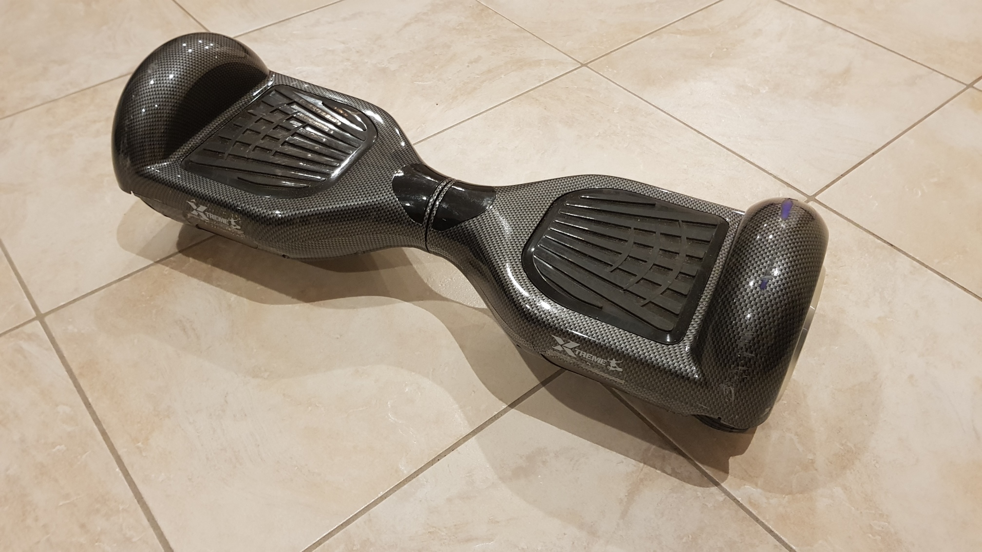
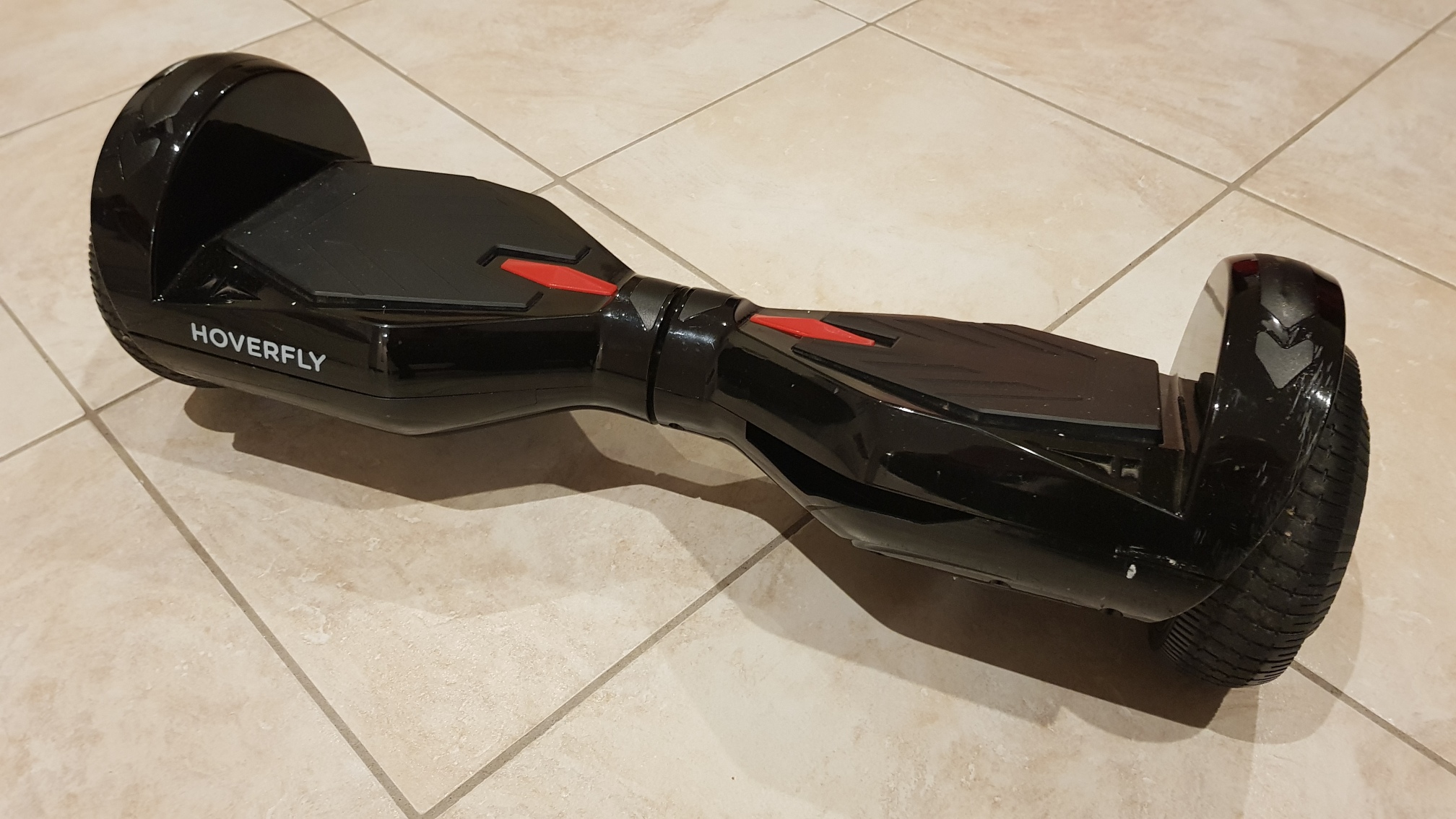
So $AU140 and a 50 minute drive and this little gem was mine.
After riding it up and down the verandah for a few hours it was time to begin the dissection.
Different approaches
There are three obvious approaches for this.
One: Using the existing protocol by reverse engineering the protocol between the boards, the rover pretends to be tipping human.
Two: Reprogram the control chip(s) in the hoverboard, and send messages from a host.
Three: Replace the hoverboard motor drivers with a driver such as the ZS-11B.
It would be nice to re-use the existing drivers: they are high quality and quite robust.
Option one: using the existing protocol
The hoverboard basically consists of one mainboard, corrected to two auxiliary boards (one on each side of the board) these are effectively left and right tilt sensors which feed 'tilt' data to the motors.
If the left side is tilting backward run the motor forward, if the left side is tilting forward run the motor backward, etc.
The 'tilt' levels are basically a speed instructions, and the left sensor controls the left motor, the right sensor controls the right motor (with some complications).
The protocol has been hacked by others, and is a bit strange.
The original hoverboard controller
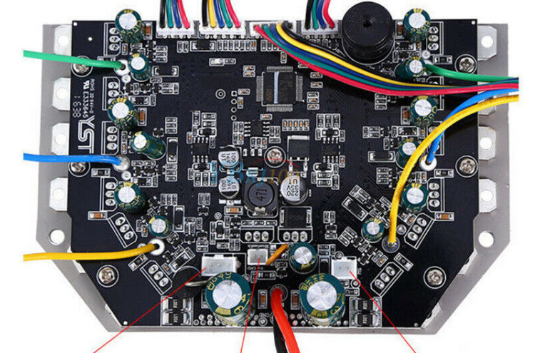
There may be a perfectly good motor driver solution within the original hoverboard - it already has a twin motor controller in it. This looks to be the most promising mechanism, but requires considerable effort to reverse engineer the protocol, even following the basic formula which others have published. Unfortunately yours truly didn't consider this option when dismantling the hoverboard, and left some of the connectors rather short.
The protocol is, apparently, 26300 baud, 9 bit (!!!) bytes with no parity. One start bit, one stop bit, in 6 byte packets. Normally bit-bashing two pins at this speed wouldn't be recommended on an Arduino Nano, but we can take some short-cuts.
One start-bit one stop-bit.
The baud rate is 26300.
There are nine (yes nine) bits to the byte.
Data is in six byte packets.
Packet structure is.
| byte 0 | 0x100 | header byte |
|---|---|---|
| byte 1 | LSB | Least significant eight bits of speed (LS bit first) |
| byte 2 | MSB | Most significant eight bits of speed (LS bit first) |
| byte 3 | LSB | Least significant eight bits of speed (LS bit first) (again!) |
| byte 4 | MSB | Most significant eight bits of speed (LS bit first) (again!) |
| byte 5 | 0x055 | trailer byte |
Possible working plan
Ideally, an Arduino Nano can be used to control the motor driver. A 3.3 volt Nano could be used (though these seem to operate at only half-speed (8MHz instead of 16HMz)). Or a 5V Nano could be used with a logic level converter. A version of SoftSerial has been written to handle the 9-bit bytes, but an Arduino Nano will still struggle to read two inputs at 26300 baud. But it doesn't have to. The serial communication actually goes both ways, but just controlling the motor controllers only requires sending, not receiving. Further, the communication on the two paths is almost identical, so there is an easier way.
So:
- The clock times can be used to interrupt every 608 clock ticks, (ie 26300 times a second at 16MHz).
- The interrupt just needs to set the outputs for the left and right ports to send the bits.
- This interrupt needs to complete as fast as possible.
- It will have to send start bits, stop bits, and pause between packets.
- Rather than use logic to work out whether to send start, stop, or pause, those bits can be pre-computed in a pre-computed bit mask of 77 bits (6 bytes of 1-stop-bit + 9-data-bits + 1-start-bit, and 11 rest bits at the end).
- The 77 bits can be stored in seven 16-bit words, with only the LS 11 bits used in each word.
- Then the 77 bits can be just cycled through by the clock interrupt.
- If the speed needs to be changed, the bits can be rewritten.
While this is a possible way forward, it hasn't been explored further. One of the issues is that later first-generation hoverboards have one of the tilt sensor boards combined with the mainboard, so there (presumably) no serial interface for it. The other issue is that second-generation hoverboards don't have a mainboard at all, just two tilt sensor boards with the motor drivers on them. Hence this just won't work.
This option has not yet been explored further.
Option two: reprogram the control chips
People smarter than me have hacked the first-generation hoverboards mainboard. This git repository is a hack of the original mainboard. I have gotten it to work on two mainboard which looks similar to the one pictured, using the STM32 Cube Programmer. Details are in the notes below.
I have two other Gen-1 mainboards, which have not worked with this approach. They have different processor chips, and don't seem to be recognised by the STM32CubeProgrammer. Details are below.
Option three: replace the motor drivers
If the existing controllers which come with the hoverboard can't be made to behave themselves there is always a plan-C: buy some motor controllers. These will not be the standard DC drivers (eg Sabertooth) used for (brushed) wheelchair motors. These are permanent magnet brushless DC motors drivers.
BLD-300B Controllers
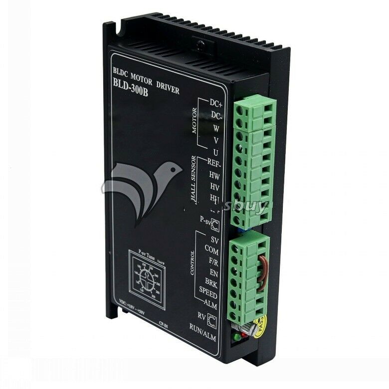
This looked like a solid (though expensive) option with lots of positive interweb reviews, but:
ZS-X11B controller
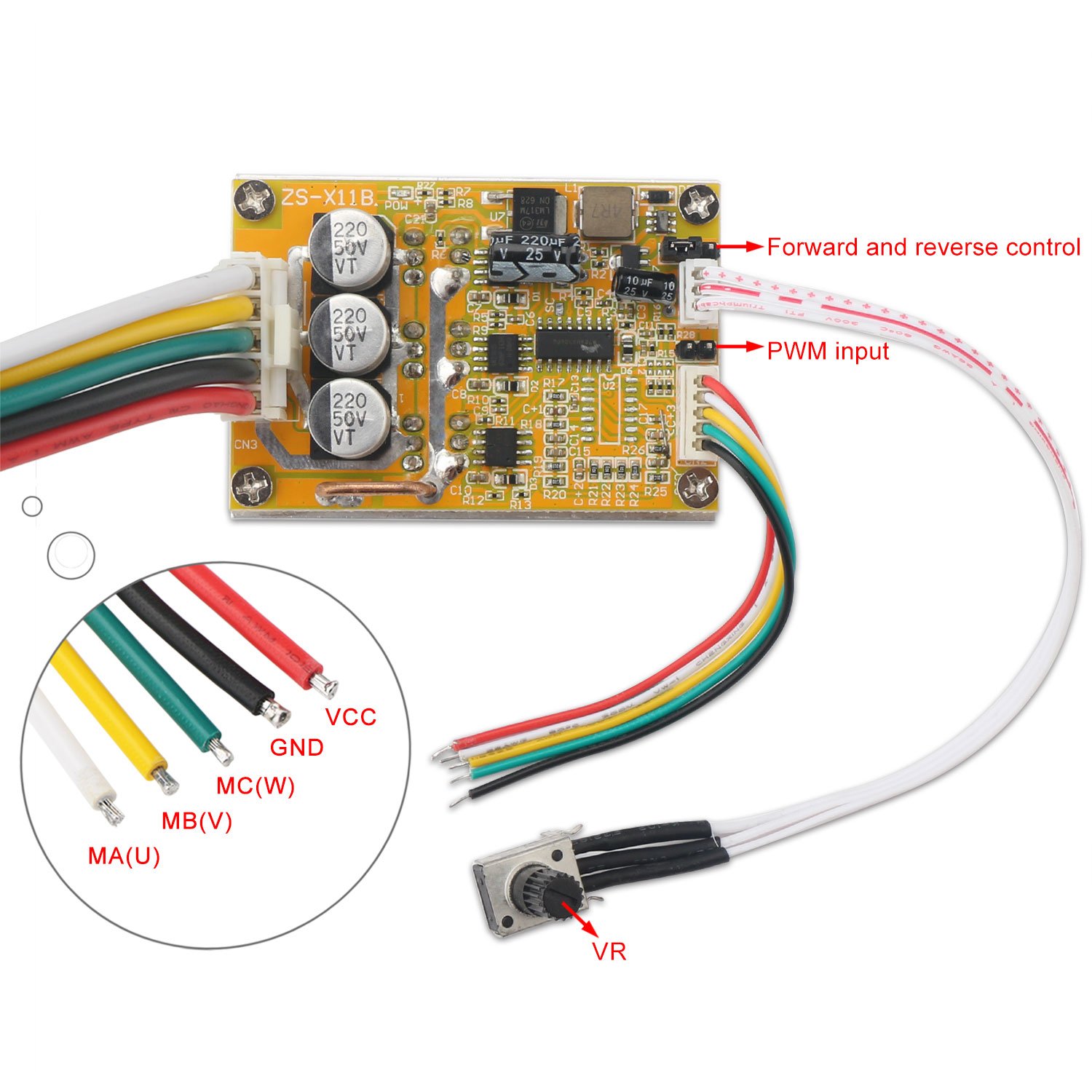
These are cheap and available on eBay/Amazon/AliExpress. Many buyers on the interweb have complained that they get a different model than the one they ordered (the sellers can't tell the difference between a (Hall-less) ZS-X11A and a (Hall enabled) ZS-X11B, but you take your chances). They are quite cheap and powerful enough for a light rover, and can be controlled by PWM on an Arduino (but see the issues below).
Execution - replace BLDC motor drivers
So $AU140 and a 50 minute drive and this little gem was mine.
After riding it up and down the verandah for a few hours it was time to begin the dissection.
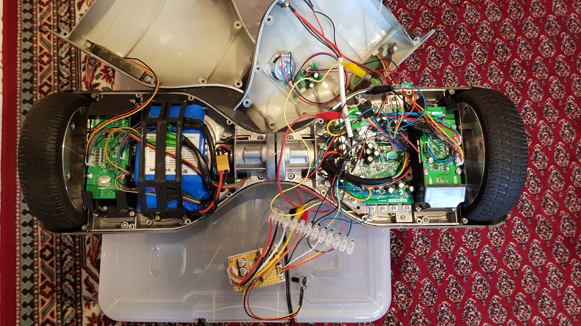
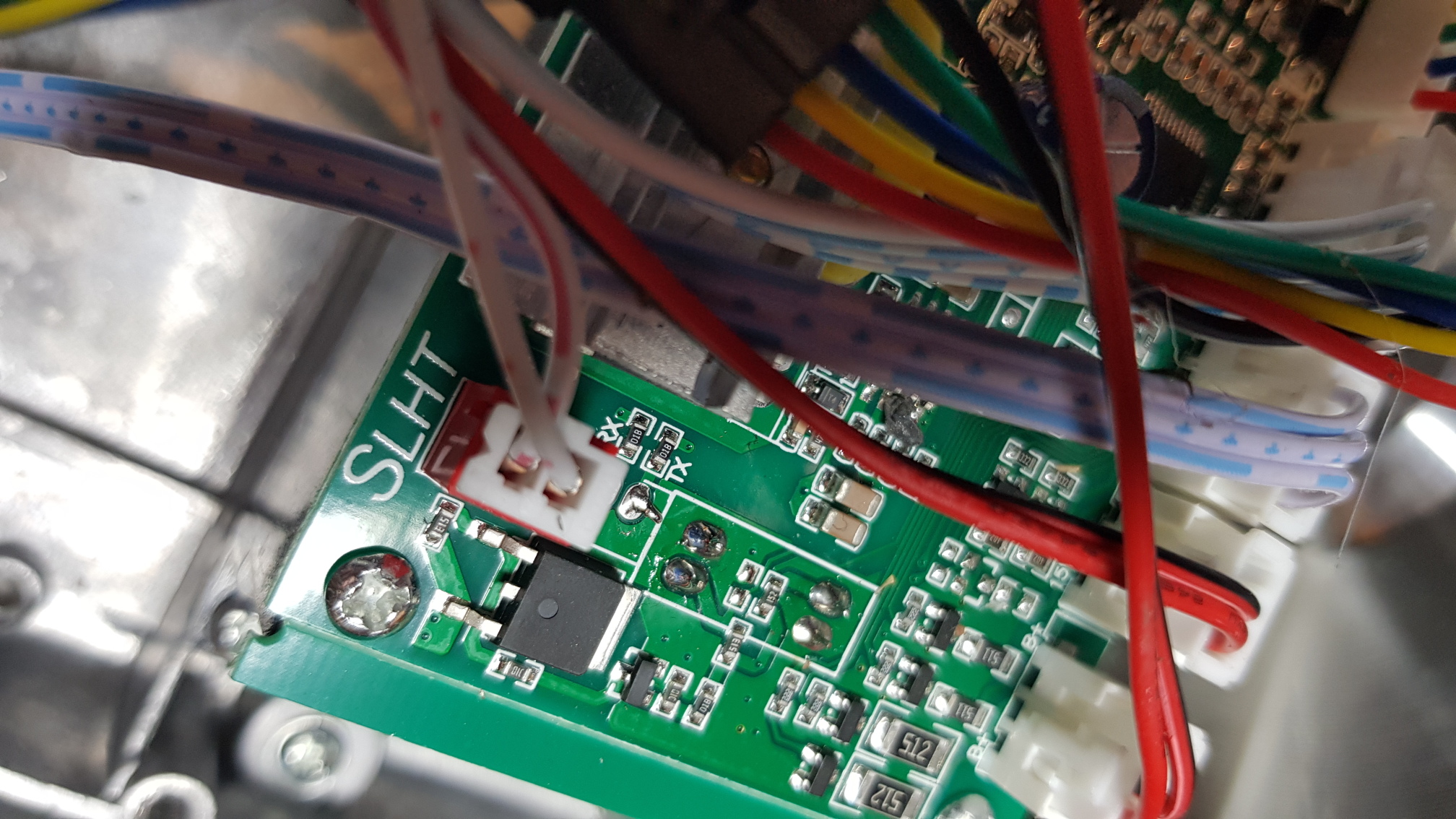
And here it it is with all its inner glory laid bare, with a single BLDC (Brushless DC) motor controller connected to one of the motors.
Note the ZS-X11B BLDC motor controller. I ordered a ZS-X11A on eBay, so of course they sent me a ZS-X11B. Thanks guys.
Apparently this is pretty standard from the suppliers of these things. So I ordered another one the same, and got lucky - they made exactly the same mistake again so I got two the same (I could hardly have demanded a refund of an item on the grounds that they sent me the right one this time!) The ZS-X11B relies on Hall sensors, but that's okay - the motors have them.
In fact this worked out well - Hall sensors are actually critical for manoeuvring at low speeds.
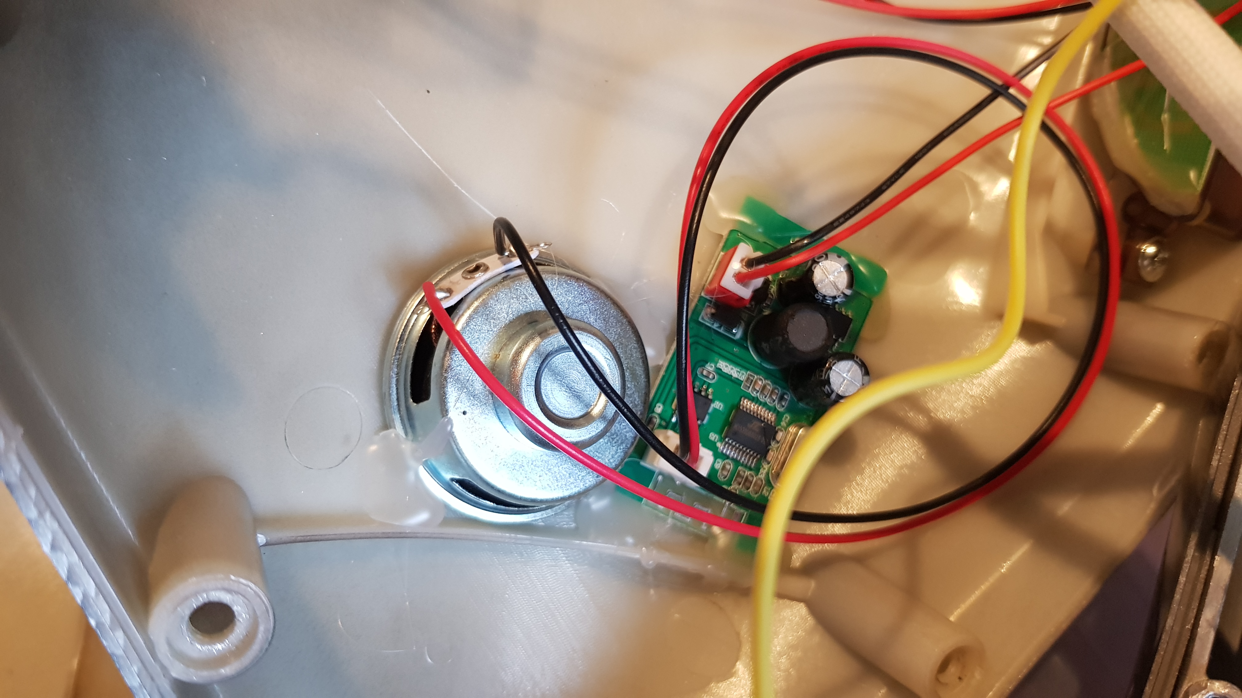
Here are two detailed photos for anyone who wants to look at the circuitry.


And here is a close-up of (I presume) the built-in bluetooth speaker.
Controlling the ZS-X11B with an Arduino
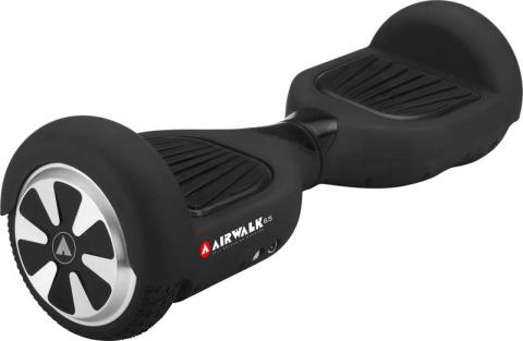
There are actually several types of ZS-X11B boards. The one I used has a pin pair between the hall sensors marked "PWM" for PWM input, and another three-pin group with a jumper (almost, but not quite like the one pictured). The jumper goes on the middle pin, and one other (one CW or ACW direction). So- GND from the Arduino connects to the GND pin on the PWM jumper. This is the one closest to the outside of the board (not labelled in the pictured version).
- A PWM output from the Arduino is connected to the PWM input pin on the PWM jumper. This is the on the inside of the board (not labelled in the pictured version).
- A digital output from the the Arduino goes to the middle pin of the CW/ACW pin trio (ie the outer pins seem to be 5V and GND, and the middle one is the input to the motor controller.

WARNING: Drive Failure with the ZS-X11Bs
Later testing suggested a problem with the ZS-X11B BLDC motor drivers which took a long time to work around.
When the rover is actually being run, the motors would just cut out, and not respond to the signals from the Arduino. On further investigation, the ZS-X11B drivers were shutting down, and required a full power cycling to reset them (they don't have a 'reset' pin).
I thought this was caused by the frequent reversing of the motors as the rover changed direction, but this was not the case. Modifications to only run the motors in one direction (ie never run either motor backwards) did not work - the drivers still crashed.
The solution was simple, but took much longer to find than it should have - the trick is to never actually fully stop the motors.
The Arduino Nano is used to drive the ZS-X11B, and driven by PWM via
analogWrite(motorSpeedPin, motorPower);
one line of code
if (motorPower < 4) motorPower = 4; // NEVER go to absolute zero. Anything less than 4 seems to causes the ZS-X11B to crash.
Seemed to save the day, except that the rover would never actually stop - it would move slowly like a Tesla in 'creep' mode.
 So the second solution was to use relays to turn off the power to the ZS-X11Bs whenever the power is set to zero (for more than 500ms).
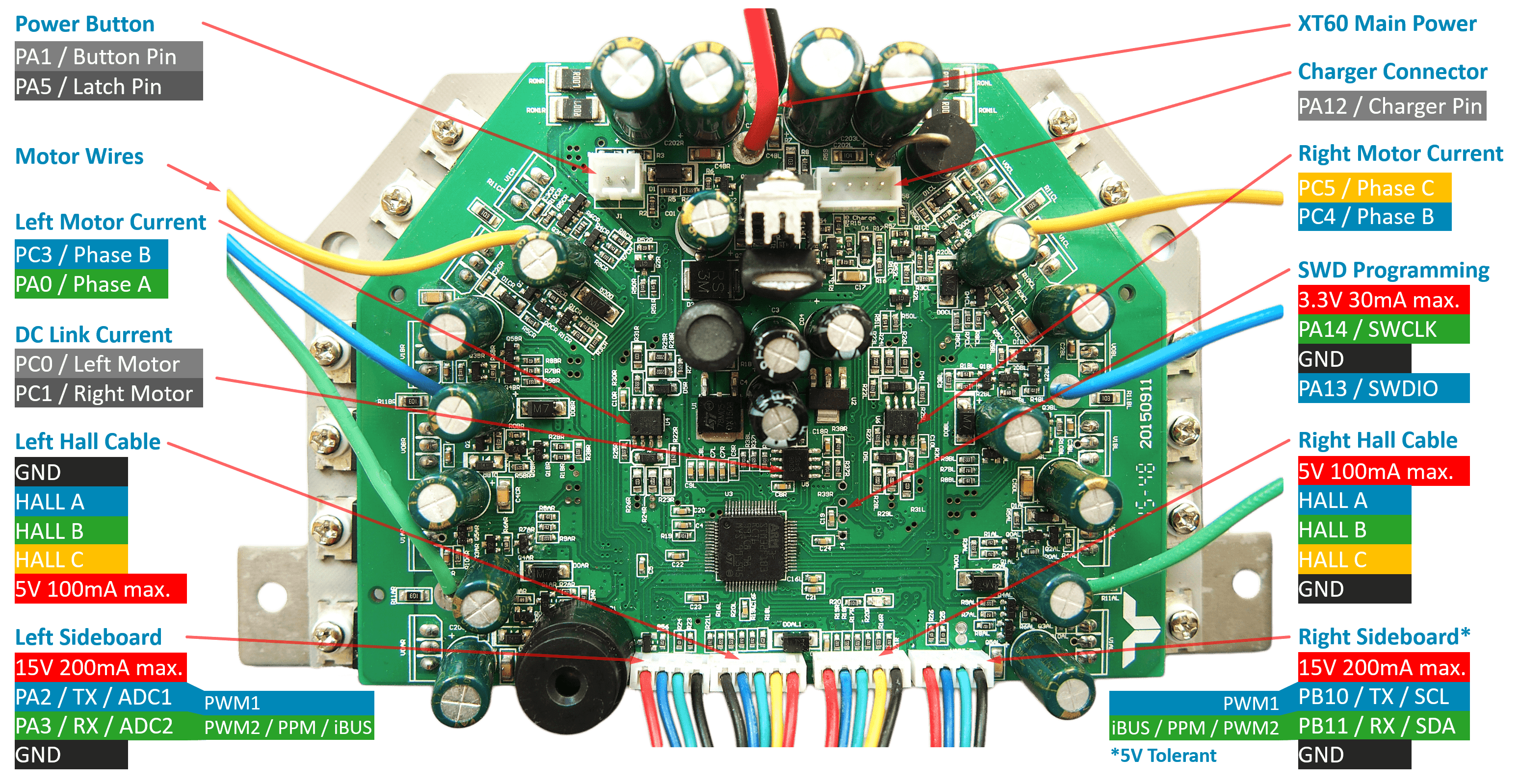
Execution - first generation hoverboard
Gen-1 mainboard mainboard (STM32F103 processor) and a side board
- The main board was removed, and 4-pin header soldered on. The square pin ("pin 1") was marked before the header went on, because the header will cover it up.
- The STM32CubeProgrammer downloaded and installed.
- The pins on the board had to be identified (there doesn't seem to be a standard for this.
- On the board marked "685586 94V-0 E253642 Y-D G2 20160617", the pins are SWDIO GND SWCLK 3.3V (SWDIO is the square pin, ie "pin 1").
- GND to SWDIO is 3.3V, GND to 3.3 is 3.3V, GND to SWCLK is around 0.2V (this is useful to track other board layouts which have the pins in different order).
- Get the ST-LINK V2 STM8 (& STM32 USB?) interface was used.
- Connect STM32CubeProgrammer ---- ST-LINK ---- 4_pin_header.
- Connect, and you should bee "Error: data read failed" because it is locked.
- Install the hoverboard program: git clone https://github.com/EFeru/hoverboard-firmware-hack-FOC.git
- This includes the hoverboard program hover.hex, but this will made to be rebuild.
- sudo apt install gcc-arm-none-eabi to get the appropriate compiler.
- Edit Inc/config.h to define VARIANT_USART, and also the COMMAND on USART3, and FEEDBACK on USART3.
                $ make clean
                $ make
Issues with using USB/serial converter
- 1. Clearly this must be done with USART3 (which is 5V tolerant) and not USART2 (which is not).
- 2. However I could not get this work with a USB/Serial converter. The number of bytes read was pretty much correct, but the values of the bytes were scrambled - presumably because the 3.3V wasn't high enough to read properly.
- 3. The Arduino example code worked a treat (but the BAUD rate had to be slowed down to 19200 so that AltSoftSerial on the Arduino Nano could keep up. Even then it drops about one in four FEEDBACK packets - presumably because of the 5V issue, not because it can't keep up with the speed.
- 4. A 3.3V processor like the ESP based chips would likely work a treat, but I am waiting on a breakout board for them.
Header pins on other hoverboards
On other hoverboard boards:- On The BLACK BOARD mainboard with the AT32F403RCT6 processor pins are P1: GND; P2: 3.3V (either 3V3 or SWDIO); P3: 0V (presumably SWCLK); P4: 3.3V (either 3V3 or SWDIO). Response of board suggests P1: GND; P2: SWDIO; P3: SWCLK; P4: 3V3. This gets result: "Error: Cannot identify the device" from STM32CubeProgrammer, presumably because the AT32F403RCT6 is unrecognised.
- On the GREEN BOARD mainboard (Cut from first hoverboard (with STM32F103 processor): P1: 3V3; P2: GND; P3: 0V; P4 3V3. Response of board suggests P1: 3V3; P2: GND; P3: SWCLK; P4: SWDIO. This gets result "Error: No STM32 target found" from STM32CubeProgrammer, the reason is not known.
- On the BLUE BOARD mainboard (Cut from older off-road-hoverboard (with STM32F103 processor): P1: 3V3, P2: 0V, P3: GND, P4: 3V3. (P1 is the square pad). Programmer reponds to P1: 3V3, P2: CLK, P3: GND P4: SWDIO.
Changes to hoverboard-firmware-hack-FOC/Inc/config.h
- The following changes were made to hoverboard-firmware-hack-FOC/Inc/config.h
$ diff config.h config.h.ORIG
14c14
<   #define VARIANT_USART       // Variant for Serial control via USART3 input
---
>   //#define VARIANT_USART       // Variant for Serial control via USART3 input
315,316c315,316
<   //#define CONTROL_SERIAL_USART2  0    // left sensor board cable, disable if ADC or PPM is used! For Arduino control check the hoverSerial.ino
<   //#define FEEDBACK_SERIAL_USART2      // left sensor board cable, disable if ADC or PPM is used!
---
>   #define CONTROL_SERIAL_USART2  0    // left sensor board cable, disable if ADC or PPM is used! For Arduino control check the hoverSerial.ino
>   #define FEEDBACK_SERIAL_USART2      // left sensor board cable, disable if ADC or PPM is used!
319,320c319,320
<   #define CONTROL_SERIAL_USART3  0    // right sensor board cable. Number indicates priority for dual-input. Disable if I2C (nunchuk or lcd) is used! For Arduino control check the hoverSerial.ino
<   #define FEEDBACK_SERIAL_USART3      // right sensor board cable, disable if I2C (nunchuk or lcd) is used!
---
>   // #define CONTROL_SERIAL_USART3  0    // right sensor board cable. Number indicates priority for dual-input. Disable if I2C (nunchuk or lcd) is used! For Arduino control check the hoverSerial.ino
>   // #define FEEDBACK_SERIAL_USART3      // right sensor board cable, disable if I2C (nunchuk or lcd) is used!
335c335
<   #define TANK_STEERING              // use for tank steering, each input controls each wheel
---
>   // #define TANK_STEERING              // use for tank steering, each input controls each wheel
467c467
<   #define USART3_BAUD             /*115200*/ 19200
---
>   #define USART3_BAUD             115200
646c646
<   #define USART2_BAUD           /*115200*/ 19200                  // UART2 baud rate (long wired cable)
---
>     #define USART2_BAUD           115200                  // UART2 baud rate (long wired cable)
652c652
<   #define USART3_BAUD           /*115200*/ 19200                  // UART3 baud rate (short wired cable)
---
>     #define USART3_BAUD           115200                  // UART3 baud rate (short wired cable)
Execution - second generation board (mini)
A small/cheap child's hoverboard. This one was a very cheap construction - the main base wasn't even metal, but plastic and the clamps over the wheel/axle flats was metal, but stamped instead of cast.
The battery was also a fraction of the size of the normal battery.
But it is a good experimental base.
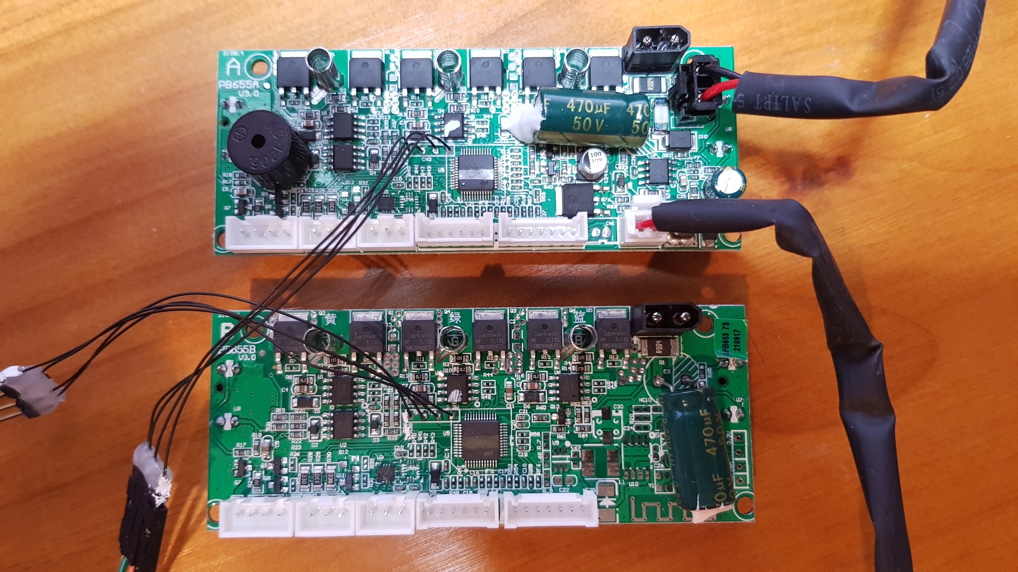
This is a 'second generation' motherboard. Instead of a mainboard, there are just two boards 'A' and 'B', each with their own tilt mechanisms, and the three H-bridges (each has a pair of mosfets) for the motor driver.
In this example, the JTAG header has already been broken out using very fine wires (because the holes were too small for my headers, and I didn't have a drill bit small enough to enlarge them risking damage to the PCB).
Chips
Chip on 'A' board is
            GD32E230
            C8T6
JTAG header on board 'A' (and probably board 'B' frankly) is
            PIN 1: 3V3  3V3   (square solder pad)
            PIN 2: ~0V  SWCLK
            PIN 3: 3V3  SWDIO
            PIN 4: GND  GND
Running STM23CubeProgrammer on this gives:
            22:17:19 : ST-LINK SN  : 34005300050000573650534E
            22:17:19 : ST-LINK FW  : V2J29S7
            22:17:19 : Board       : --
            22:17:19 : Voltage     : 3.26V
            22:17:19 : SWD freq    : 4000 KHz
            22:17:19 : Connect mode: Normal
            22:17:19 : Reset mode  : Software reset
            22:17:19 : Device ID   : 0x410
            22:17:19 : Revision ID : --
            22:17:19 : Debug in Low Power mode is not supported for this device.
            22:17:19 : UPLOADING OPTION BYTES DATA ...
            22:17:19 :   Bank          : 0x00
            22:17:19 :   Address       : 0x4002201c
            22:17:19 :   Size          : 8 Bytes
            22:17:19 :   Bank          : 0x01
            22:17:19 :   Address       : 0x1ffff800
            22:17:19 :   Size          : 16 Bytes
            22:17:19 : UPLOADING ...
            22:17:19 :   Size          : 1024 Bytes
            22:17:19 :   Address       : 0x8000000
            22:17:19 : Read progress:
            22:17:20 : Error: Data read failed
According to
http://community.st.com/s/question/0D53W00000bfw5CSAQ/discrepancy-chip-marking-vs-productchip-id-my-chip-marked-stm32f100v8t6b-give-a-productid-0x414-while-i-expected-0x420-have-i-received-a-batch-of-chips-with-an-incorrect-marking
Device ID 0x410 is Series: STM32F1, Name: STM32F101/F102/F103 Medium-density, CPU: Cortex-M3, Vendor STMicroelectronics.
Promising github repositories
Execution: second generation off-road hoverboards.
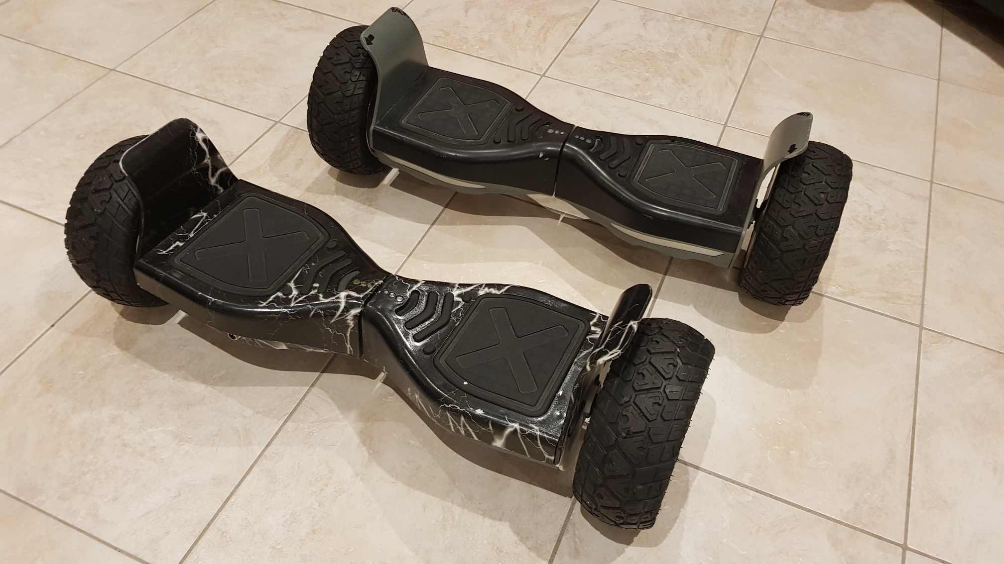
Never judge a hoverboard by its cover. These two hoverboards look the same, but they have completely different driver boards. One has a first generation mainboard and tilt boards, and the other has two second generation boards in it.
Off-road hoverboard 1

This one has an old fashioned first generation board. The chip is:
              GD32F130
              C6T6
              CE94O90
              AJ1923
              ARM
The following repositories may be usefulhttps://github.com/JRomainG/GD32F130K6-hoverboard-hack
https://github.com/EFeru/hoverboard-sideboard-hack-GD
Off-road hoverboard 2
Off-road hoverboard1 uses two boards the MASTER and SLAVE. The chip is:
              ARM3
              STM32F103
              RTC6
              9911N 98
              MYS 99 546

Leave a comment
 Something I'm doing wrong? Solved my problems? Got a better idea? Got a similar problem?
Think I might have solved your problem? Ninety-nine problems, but your robot ain't one? Say so ..